
User guide
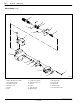

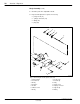

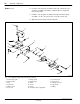
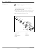
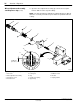
Table Of Contents

AccuJet
Dispenser
31
1998 Nordson Corporation
All rights reserved
107 142B
Issued 4/98
Manual 12-34
CAUTION: Handle O-rings and seals carefully. If O-rings or
seals are damaged, leakage or premature dispenser failure
may occur.
CAUTION: Protect the solenoid valve from contact with coating
material or solvent. Contamination could cause solenoid failure.
NOTE: Assemble the AccuJet dispenser on a flat surface. The screws
should be tightened to a torque of 3–5 inch-pounds except where noted
in the assembly instructions.
See Figure 7.
1.Install a U-cup seal (6), spring side facing out, into the lower body (4).
Using the ring and seal insertion tool, carefully seat the U-cup seal (6)
into the lower body.
2.Using the ring and seal insertion tool, carefully seat the O-ring (7) into
the lower body (4).
3.Install a U-cup seal (6), spring side facing out and up, into the
upperbody (16). Using the ring and insertion tool, carefully seat the
U-cup seal into the body.
4.Screw the fitting (17) and plug (3) into the upper body (16).
5.Place the dispenser bodies on their backs. Mate the upper body (16)
with the lower body (4) and secure with the fillister screws (5).
6.Screw the syringe connector (15) and purge screw (14) into the
lowerbody (4).
7.Install the solenoid valve (2) on the upper body (16) and secure using
socket head screws (1).
See Figure 7.
1.Apply conductive grease (12) on the seat extension (13) as
illustrated. Do not put grease on the threads.
NOTE: Make sure that the dowel-pin hole on the seat extension faces
toward the backside of the applicator.
8. Assembly
Body Assembly
Heater