AccuJett Dispenser Customer Product Manual Part 107 142B NORDSON CORPORATION D AMHERST, OHIO D USA
Nordson Corporation welcomes requests for information, comments and inquiries about its products. Address all correspondence to Nordson Corporation 555 Jackson Street Amherst, OH 44001 Notice This is a Nordson Corporation publication which is protected by copyright. Original copyright date 1997. No part of this document may be photocopied, reproduced, or translated to another language without the prior written consent of Nordson Corporation.
Table of Contents i Table of Contents 1. Introduction . . . . . . . . . . . . . . . . . . . . . . . . . . . . . . . . . . . . . . . . . . . . . . . . . 1 Safety Symbols . . . . . . . . . . . . . . . . . . . . . . . . . . . . . . . . . . . . . . . . . . . 1 Qualified Personnel . . . . . . . . . . . . . . . . . . . . . . . . . . . . . . . . . . . . . . . 3 Intended Use . . . . . . . . . . . . . . . . . . . . . . . . . . . . . . . . . . . . . . . . . . . . . 3 Installation . . . . . . . . . . . . . . . . . .
ii Table of Contents 8. Assembly . . . . . . . . . . . . . . . . . . . . . . . . . . . . . . . . . . . . . . . . . . . . . . . . . 31 Body Assembly . . . . . . . . . . . . . . . . . . . . . . . . . . . . . . . . . . . . . . . . . . 31 Heater . . . . . . . . . . . . . . . . . . . . . . . . . . . . . . . . . . . . . . . . . . . . . . . . . . 31 Air Piston . . . . . . . . . . . . . . . . . . . . . . . . . . . . . . . . . . . . . . . . . . . . . . . 33 Micro-Adjustment Assembly and Dispenser Cap . . . . . . .
AccuJett Dispenser 1 AccuJett Dispenser 1. Safety This section contains general safety instructions for using Nordson equipment. Task- and equipment-specific warnings are included in other sections of this manual where appropriate. Note all warnings and follow all instructions carefully. Failure to do so may result in personal injury, death, or property damage.
2 AccuJet Dispenser Safety Symbols (contd) WARNING: Risk of electrical shock. Failure to observe this warning may result in personal injury, death, or equipment damage. WARNING: Disconnect equipment from line voltage. Failure to observe this warning may result in personal injury, death, or equipment damage. WARNING: Risk of explosion or fire. Fire, open flames, and smoking prohibited. WARNING: Wear protective clothing, safety goggles, and approved respiratory protection.
AccuJett Dispenser Safety Symbols (contd) 3 CAUTION: Failure to observe may result in equipment damage. CAUTION: Hot surface. Failure to observe may result in burns. Qualified Personnel Intended Use “Qualified personnel” is defined here as individuals who thoroughly understand the equipment and its safe operation, maintenance, and repair.
4 AccuJett Dispenser Installation Read the installation section of all system component manuals before installing your equipment. A thorough understanding of system components and their requirements will help you install the system safely and efficiently. WARNING: Failure to follow these safety procedures can result in personal injury or death. S Allow only qualified personnel to install Nordson and auxiliary equipment. Use only approved equipment.
AccuJett Dispenser Installation (contd) 5 S Make sure the spray area floor is conductive to ground and that the operator’s platform is grounded. S Do not use unapproved fluid hoses. Solvents may cause them to deteriorate rapidly which may allow flammable liquids or pressurized material to escape. S Protect components from damage, wear, and harsh environmental conditions. S Allow ample room for maintenance, material supply container drop-off and loading, panel accessibility, and cover removal.
6 AccuJett Dispenser Operation (contd) S Know where EMERGENCY STOP buttons, shutoff valves, and fire extinguisher are located. Make sure they work. If a component malfunctions, shut down and lock out the equipment immediately. S Know the pinch points, temperatures, pressures, and dispense material composition for all equipment that you are working with. Recognize potential hazards associated with these and exercise appropriate caution.
AccuJett Dispenser Operation (contd) 7 S Wash exposed skin frequently with soap and water, especially before eating or drinking. Do not use solvents to remove coating materials from your skin. S High-pressure compressed air can be injected under the skin and cause serious injury or death. Treat all high-pressure fittings and hoses as if they could leak and cause injury. S Never point film coaters or nozzles at yourself or other persons. S Do not smoke in the spray area.
8 AccuJett Dispenser Maintenance and Repair Allow only qualified personnel to perform maintenance, troubleshooting, and repair tasks. Only persons who are properly trained and familiar with Nordson equipment are permitted to service this equipment. S Always wear appropriate protective clothing and use safety devices when working on this equipment. S Follow the recommended maintenance procedures in your equipment manuals.
AccuJett Dispenser Maintenance and Repair (contd) 9 S Check interlock systems periodically to ensure their effectiveness. S Check all ground connections periodically with a megohm meter. Resistance to ground must not exceed one megohm. If sparks or arcing occur, shut down the system immediately. S Disconnect, lock out, and tag electrical power at a disconnect or breaker in the service line ahead of electrical equipment before servicing.
10 AccuJett Dispenser Material and Solvent Precautions (contd) High-pressure fluids, unless they are safely contained, are extremely hazardous. A jet of high-pressure fluid can act like a knife or needle, penetrate skin and muscle, and inject itself into your body. Injected fluids can cause toxic poisoning. Do not treat an injection injury as minor. Seek medical care immediately. Inform the medical staff at the hospital that you have an injection injury and identify the fluid that was injected.
AccuJett Dispenser Material and Solvent Precautions (contd) 11 Halogenated hydrocarbon solvents can cause an explosion when used with aluminum components in a pressurized fluid pumping system (pumps, heaters, filters, valves, spray guns, and tanks). The explosion could cause serious bodily injury, death, or substantial property damage. No available stabilizers will prevent this violent reaction from happening.
12 AccuJett Dispenser S Contact your coatings, solvent, or adhesive supplier for a Material and Solvent Precautions (contd) nonhalogenated solvent to thoroughly flush the entire system before operating it. S If you must continue to use halogenated hydrocarbon solvents, consult your Nordson representative about compatible Nordson components.
AccuJett Dispenser 2. Description 13 See Figure 1. The AccuJet dispenser applies adhesive dots on circuit boards before surface-mounted electrical components are installed. See Figure 2. A syringe (2) of adhesive connects to the dispenser. Adhesive flows from the syringe at 0.35–2.1 bar (5–30 psi) and into the fluid chamber. The heater (7) warms the adhesive to 40 to 55 _C (104–131 _F) to reduce viscosity and improve flow characteristics.
14 AccuJet Dispenser 3. Installation NOTE: Dispenser installation is dependent upon the workcell. Consult your Nordson representative if more information is necessary. See Figure 2. 1. Use the mounting screws (5) to install the dispenser on the robot mounting plate (4). Tighten the screws securely. 2. Connect the solenoid valve connector (1) to the 24 volt timed-control signal. NOTE: The control signal must be able to maintain 18–24 Vdc when the signal is on. 3.
AccuJet Dispenser 15 2 3 1 4 5 11 10 8 7 9 6 1234001A Fig. 2 AccuJet dispenser 1. 2. 3. 4. Solenoid valve connector Syringe Micro-adjustment assembly Robot mounting plate 1998 Nordson Corporation All rights reserved 5. 6. 7. 8. Mounting screws Nozzle Heater Solenoid valve 107 142B Issued 4/98 9. Heater connector 10. Syringe connector 11.
16 AccuJett Dispenser 4. Operation WARNING: Allow only qualified personnel to perform the following tasks. Follow the safety instructions in this document and all other related documentation. NOTE: Operation of the dispenser is dependent upon the workcell. Consult your Nordson representative if more information is necessary. 1. Turn on the supply air to your workcell. 2. Set the solenoid air pressure to 5.5 bar (80 psi) and check for leaks. 3. See Figure 2. Remove the nozzle (6).
AccuJett Dispenser 17 Table 2 AccuJet Set-Points Item 5. Maintenance Setting Micro-adjust _______ mm Preload _______ turns Temperature ______/______ _C/_F Syringe pressure ______/______ bar/psi Solenoid pressure ______/______ bar/psi WARNING: Allow only qualified personnel to perform the following tasks. Follow the safety instructions in this document and all other related documentation. Follow these procedures to clean and maintain the AccuJet dispenser.
18 AccuJet Dispenser Nozzle 1. See Figure 3. Clean the nozzle (7) with a solvent that is recommended for the adhesive. Contact your material supplier for recommended solvents. 2. Use an air gun to blow out the nozzle (7) and clear the fluid passage. Submerge the nozzle in an ultrasonic cleaning system to remove remaining material. CAUTION: Use the correct cleaning wire to prevent damage to the nozzle. 3. Use a microscope to inspect the nozzle (7).
AccuJett Dispenser 19 Disassembly 1. See Figure 3. Turn the micro-adjust cap (1) 4 to 5 turns counterclockwise. 2. Use the spanner wrench to loosen the locking nut (3). Turn the preload screw (2) to relieve compression on the spring. 3. Use the 7/64-in. hex key to remove the screws (6) securing the heater (5) and the seat extension (9) to the lower body (4). Separate the extension from the heater. Either discard the O-ring (10) or wipe it with a towel. 4.
AccuJet Dispenser 20 Disassembly (contd.) 1 2 3 4 17 16 13 12 11 15 5 10 9 14 8 7 6 1234002A Fig. 3 Dispenser cleaning 1. 2. 3. 4. 5. 6. Micro-adjustment cap Preload screw Locking nut Lower body Heater Screw Manual 12-34 7. 8. 9. 10. 11. 12. Nozzle Conductive grease application Seat extension O-ring (large) O- ring (small) U-cup seal 107 142B Issued 4/98 13. 14. 15. 16. 17.
AccuJet Dispenser 21 Assembly CAUTION: To prevent damage to the seat, make sure that the micro-adjust is opened 4–6 turns. NOTE: Assemble the AccuJet dispenser on a flat surface. The screws should be tightened to 0.3–0.6 N•m (3–5 lb-in.) except where noted in the assembly instructions. 1. See Figure 3. Insert the O-ring (11) into the lower body (4). 2. Carefully install the lower body (4) on the upper body (17) and secure using the screws (14). 3. Install the purge screw (15) into lower body (4).
22 AccuJet Dispenser Assembly (contd.) 10. Use the spanner wrench to lock the locking nut (3) to the face of the upper body (17). 11. Turn the micro-adjustment cap (1) to gently seat the needle into the extension. Open the micro-adjustment cap counterclockwise to the desired setting (Refer to Table 2 for settings). 12. Remove the nozzle (7) from the seat extension (9). 13. Install the syringe connector (16) into the lower body (4). 14. Refer to Operation for operating procedures.
AccuJet Dispenser 23 WARNING: Allow only qualified personnel to perform the following tasks. Follow the safety instructions in this document and all other related documentation. 6. Troubleshooting This section contains troubleshooting procedures. These procedures cover only the most common problems that you may encounter. If you cannot solve the problem with the information given here, contact your local Nordson representative for help. Problem 1998 Nordson Corporation All rights reserved Page 1.
24 AccuJett Dispenser 6. Troubleshooting (contd.) Problem 1. 2. 3. Dispenser does not cycle Fluid leaks from weep hole Adhesive dots do not form Possible Cause Corrective Action No signal to solenoid valve Check the solenoid connections between the workcell and the dispenser. Air pressure to solenoid valve is off or insufficient Make sure that air pressure is 5–6 bar (70–90 psi). Worn seal or needle Inspect the needle and seal for excessive wear. Replace parts, if necessary.
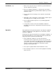
AccuJett Dispenser Problem 5. 6. 7. 8. 9. Dots are too big Dots are too small Dots are not round Too many satellites forming Dots are too flat 10. Dots are too tall E 1998 Nordson Corporation All rights reserved Possible Cause 25 Corrective Action Wrong nozzle size Use a smaller nozzle. Too many shots per dot Decrease the number of shots per dot. Micro-adjustment open to far; excessive needle stroke Decrease the micro-adjust setting to reduce the needle stroke.
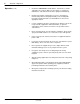
26 AccuJett Dispenser 7. Repair WARNING: Allow only qualified personnel to perform the following tasks. Follow the safety instructions in this document and all other related documentation. CAUTION: Handle O-rings and seals carefully. If O-rings or seals are damaged, leakage or premature dispenser failure may occur. CAUTION: Protect the solenoid valve from contact with coating material or solvent. Contamination could cause solenoid failure.
AccuJett Dispenser Disassembly 27 The following paragraphs provide disassembly procedures for the AccuJet dispenser. Micro-Adjustment Assembly See Figure 5. CAUTION: Back off the micro-adjustment assembly to prevent damage to the needle and seat during assembly. 1. Inspect the micro-adjustment assembly (1) for damage: S If damaged, loosen the preload set screws (2) and replace the assembly. S If no damage is found, turn the micro-adjustment 4–6 turns counterclockwise to increase its setting. 2.
28 AccuJet Dispenser Disassembly (contd) 1 2 3 4 2 6 7 17 5 16 15 14 13 12 11 10 8 9 1234004A Fig. 5 Dispenser disassembly 1. 2. 3. 4. 5. 6. Micro-adjustment assembly Preload set screws Preload locking nut Preload screw Screws Cap Manual 12-34 7. 8. 9. 10. 11. 12. Compression spring Socket head screws Nozzle Heater Seat extension O-ring (large) 107 142B Issued 4/98 13. 14. 15. 16. 17.
AccuJett Dispenser 29 Body Assembly CAUTION: To prevent damage to the ball and needle, do not use tools to grip the needle threads. 1. See Figure 5. Remove the screws (5) securing the cap (6) to the upper body (15). Remove the compression spring (7). 2. See Figure 6. Remove the fillister screws (6) securing the lower body (9) to the upper body (13). 3. Carefully push the needle (5) out of the body assembly. 4. Inspect the needle (5) and the air piston (4) for damage.
30 AccuJett Dispenser Body Assembly (contd.) 8. Clean the parts in a compatible solvent. 9. Inspect and replace these parts, if necessary: S S S S purge screw (11) syringe connector (12) fitting (14) plug (10) 1 2 3 4 5 8 14 10 13 9 6 8 7 12 11 6 1234005A Fig. 6 Removing the needle, piston, and seals 1. 2. 3. 4. 5. 6. 7. Manual 12-34 Spring retainer Seal lock nut O-ring Air piston Needle Fillister screws O-ring 107 142B Issued 4/98 8. 9. 10. 11. 12. 13. 14.
AccuJet Dispenser 8. Assembly 31 CAUTION: Handle O-rings and seals carefully. If O-rings or seals are damaged, leakage or premature dispenser failure may occur. CAUTION: Protect the solenoid valve from contact with coating material or solvent. Contamination could cause solenoid failure. NOTE: Assemble the AccuJet dispenser on a flat surface. The screws should be tightened to a torque of 3–5 inch-pounds except where noted in the assembly instructions. Body Assembly See Figure 7. 1.
AccuJet Dispenser 32 2. Insert the seat extension (13) into the heater (9). Rotate the seat extension assembly to spread the conductive grease evenly and remove air pockets. Heater (contd) 3. Install the seat extension assembly on the upper and lower body assembly. Use the 7/64-in. hex key to secure the screws (10). 4. Wipe any grease from the extension threads. 1 2 3 6 4 17 16 5 6 7 8 15 14 9 13 12 5 10 11 10 1234006A Fig. 7 Assembling the upper body, lower body, and heater 1. 2. 3. 4. 5.
AccuJet Dispenser Air Piston 33 See Figure 8. 1. Insert the needle (7) through the seal in the upper body (8) and the internal seal in the lower body (9). The needle is properly seated when the needle ball contacts the end of the seat extension. 2. To properly seat the piston in the piston insertion tool (4), roll the seal lip (5) of the new air piston (6) on a clean flat surface. The seal lip must be formed so that the lip hangs down toward the dispenser. 3.
34 AccuJet Dispenser CAUTION: To prevent damage to the needle, do not over-tighten the spring retainer. Air Piston (contd) 11. Place the spring retainer (1) on the needle (7). Using the module-adjusting wrenches, hold the seal lock nut in place and tighten the spring retainer snugly. 12. Seat the needle (7). Verify that the top of the seal lock nut is flushed to within 0.25 mm (0.010 in.) above the top of the upper body (8). 13. Make sure that the ball and seat properly seats.
AccuJet Dispenser Micro-Adjustment Assembly and Dispenser Cap 35 See Figure 9. CAUTION: To prevent damage to the seat assembly, install a nozzle on the dispenser. 1. Install the cap (6) on the upper body (8) and secure using the fillister screws (9). 2. Place the compression spring (7) on the spring retainer (11). 3. Make sure the locking nut (5) is installed on the preload screw (4). NOTE: If desired, use the spanner wrench to install the preload screw. 4. Install the preload screw (4) in the cap (6).
36 AccuJet Dispenser 11. Open the micro-adjustment assembly (2) to the desired set-point. Refer to Table 2 for the set-point settings. Micro-Adjustment Assembly and Dispenser Cap (contd) NOTE: The preload and micro-adjustment settings will vary for different adhesives. Consult your Nordson representative for particular adhesive settings. 1 2 3 4 5 6 7 9 10 11 8 0.254 mm (0.010 in.) 1234008A Fig. 9 Installing the micro-adjustment assembly and cap 1. 2. 3. 4.
AccuJett Dispenser 37 To order parts, call the Nordson Customer Service Center or your local Nordson representative. Use this five-column parts list, and the accompanying illustration, to describe and locate parts correctly. 9. Parts Using the Illustrated Parts List Numbers in the Item column correspond to numbers that identify parts in illustrations following each parts list. The code NS (not shown) indicates that a listed part is not illustrated.
AccuJett Dispenser 38 AccuJet Dispenser Parts Item See Figure 10. Part Description Quantity Note A — 226 300 Applicator, adhesive, AccuJet 1 1 226 289 S Micro-adjustment, with lock 1 2 982 745 S Screw, set, preload 2 3 226 276 S Screw, preload 1 4 145 461 S Nut, locking 1 5 234 170 S Cap, end 1 6 981 029 S Screw, fillister, 6-32 x 0.500 in.
AccuJett Dispenser Item Part Description Quantity 39 Note 25 973 529 S Connector, male, barbed, M5, ss 1 26 982 746 S Screw, socket head, 4-40 x 1.00 in. 2 27 226 278 S Valve, 3-way, solenoid, 24 Vdc, 120 psi 1 28 234 154 S Plug, M5, ss 1 29 234 149 S Key, hex, 1.5 mm 1 D 30 234 150 S Key, hex, 0.050 in. 1 D 31 234 151 S Key, hex, 7/64 in. 1 D 32 129 612 S Key, hex, 3/32 in.
AccuJet Dispenser 40 AccuJet Dispenser Parts (contd) 1 2 3 4 2 5 26 7 6 27 8 9 10 11 28 12 20 25 24 17 20 19 18 23 22 21 Part of 12 17 16 13 14 15 13 1234009B Fig.
AccuJet Dispenser 41 34 29 35 30 31 36 37 32 38 39 33 1234010B Fig.
AccuJet Dispenser 42 See Figure 10. Nozzles Item Part Description Quantity 14 234 204 Nozzle, hex, with guard, 0.004 in. dia 1 14 234 205 Nozzle, hex, with guard, 0.005 in. dia 1 14 234 206 Nozzle, hex, with guard, 0.006 in. dia 1 14 234 207 Nozzle, hex, with guard, 0.007 in. dia 1 14 234 208 Nozzle, hex, with guard, 0.008 in. dia 1 14 234 209 Nozzle, hex, with guard, 0.009 in. dia 1 14 234 210 Nozzle, hex, with guard, 0.010 in.
AccuJet Dispenser Item Part Description Quantity 14 234 315 Nozzle, round, without guard, 0.015 in. dia 1 14 234 316 Nozzle, round, without guard, 0.016 in. dia 1 14 234 317 Nozzle, round, without guard, 0.017 in. dia 1 14 234 318 Nozzle, round, without guard, 0.018 in. dia 1 14 234 319 Nozzle, round, without guard, 0.019 in. dia 1 14 234 320 Nozzle, round, without guard, 0.020 in. dia 1 14 249 904 Nozzle, round, with guard, 0.004 in.
AccuJet Dispenser 44 Nozzles (contd) Item Part Description Quantity 14 249 980 Nozzle, hex, without guard, 0.010 in. dia 1 14 249 981 Nozzle, hex, without guard, 0.011 in. dia 1 14 249 982 Nozzle, hex, without guard, 0.012 in. dia 1 14 249 983 Nozzle, hex, without guard, 0.013 in. dia 1 14 249 984 Nozzle, hex, without guard, 0.014 in. dia 1 14 249 985 Nozzle, hex, without guard, 0.015 in. dia 1 14 249 986 Nozzle, hex, without guard, 0.016 in.