Model No. NTEVEX76017.0 Serial No. Write the serial number in the space above for reference. USER’S MANUAL Serial Number Decal CUSTOMER SERVICE UNITED KINGDOM Call: 0330 123 1045 From Ireland: 053 92 36102 Website: iconsupport.eu E-mail: csuk@iconeurope.com Write: ICON Health & Fitness, Ltd. Unit 4, Westgate Court Silkwood Park OSSETT WF5 9TT UNITED KINGDOM AUSTRALIA Call: 1800 993 770 E-mail: australiacc@iconfitness.
TABLE OF CONTENTS WARNING DECAL PLACEMENT . . . . . . . . . . . . . . . . . . . . . . . . . . . . . . . . . . . . . . . . . . . . . . . . . . . . . . . . . . . . . . .2 IMPORTANT PRECAUTIONS. . . . . . . . . . . . . . . . . . . . . . . . . . . . . . . . . . . . . . . . . . . . . . . . . . . . . . . . . . . . . . . . . . 3 BEFORE YOU BEGIN. . . . . . . . . . . . . . . . . . . . . . . . . . . . . . . . . . . . . . . . . . . . . . . . . . . . . . . . . . . . . . . . . . . . . . . .4 PART IDENTIFICATION CHART.
IMPORTANT PRECAUTIONS WARNING: To reduce the risk of serious injury, read all important precautions and instructions in this manual and all warnings on your exercise bike before using your exercise bike. ICON assumes no responsibility for personal injury or property damage sustained by or through the use of this product. 1. It is the responsibility of the owner to ensure that all users of the exercise bike are adequately informed of all precautions. 8.
BEFORE YOU BEGIN Thank you for selecting the new NORDICTRACK® COMMERCIAL VR 21 exercise bike. Cycling is an effective exercise for increasing cardiovascular fitness, building endurance, and toning the body. The COMMERCIAL VR 21 exercise bike provides a selection of features designed to make your workouts at home more effective and enjoyable. reading this manual, please see the front cover of this manual. To help us assist you, note the product model number and serial number before contacting us.
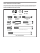
PART IDENTIFICATION CHART Use the drawings below to identify the small parts needed for assembly. The number in parentheses below each drawing is the key number of the part, from the PART LIST near the end of this manual. The number following the key number is the quantity needed for assembly. Note: If a part is not in the hardware kit, check to see if it has been preassembled. Extra parts may be included.
ASSEMBLY • Assembly requires two persons. In addition to the included tool(s), assembly requires the following tools: • Place all parts in a cleared area and remove the packing materials. Do not dispose of the packing materials until you finish all assembly steps. one Phillips screwdriver one adjustable wrench • Left parts are marked “L” or “Left” and right parts are marked “R” or “Right.” Assembly may be easier if you have a set of wrenches. To avoid damaging parts, do not use power tools.
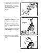
3. With the help of a second person, place some of the packing materials (not shown) under the rear of the Frame (1). 3 Attach the Rear Stabilizer (3) to the Frame (1) with two M10 x 120mm Screws (44); start both Screws, and then tighten them. Then, remove the packing material from under the Frame (1). 3 1 44 4. Have a second person hold the Upright (4) on the Frame (1). 4 Tip: Avoid pinching the Main Wire (41).
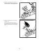
6. Attach the Accessory Tray (9) to the Upright (4) with an M6 x 50mm Screw (42). 6 42 9 7. Untie and discard the wire tie on the Main Wire (41). 4 7 82 While a second person holds the Console Bracket (82) near the Upright (4), route the Main Wire (41) through the notch in the Upright, through the Upright Bracket (84), and through the hole in the center of the Console Bracket. 84 49 41 4 102 Tip: Avoid pinching the Main Wire (41). Insert the Upright Bracket (84) into the Upright (4).
. While a second person holds the Console (5) near the Console Bracket (82), connect the wires on the Console to the Main Wire (41) and to the Left and Right Pulse Wires (7, 8). 9 5 41 82 63 Insert the excess wire into the Console Bracket (82). 63 Tip: Avoid pinching the wires. Attach the Console (5) to the Console Bracket (82) with four M4 x 15mm Screws (63); start all the Screws, and then tighten them. 7, 8 Avoid pinching the wires 10.
11. Attach the Seat Handlebar (18) to the Seat Carriage (11) with four M8 x 40mm Screws (56); start all the Screws, and then tighten them. 11 56 18 11 12. Slide the Backrest Frame (14) onto the Seat Handlebar (18). 12 Attach the Backrest Frame (14) with four M6 x 30mm Screws (51) and four M6 Washers (112); start all the Screws, and then tighten them.
13. Attach the Seat (12) to the Seat Handlebar (18) with four M6 x 20mm Screws (67) and four M6 Washers (112) (only two of each are shown); start all the Screws, and then tighten them. 13 12 18 112 14. Identify the Right Pedal (29). 67 14 Using an adjustable wrench, firmly tighten the Right Pedal (29) clockwise into the Right Crank Arm (99). Firmly tighten the Left Pedal (not shown) counterclockwise into the Left Crank Arm (not shown).
15. Plug the Power Adapter (107) into the receptacle on the frame of the exercise bike. 15 Note: To plug the Power Adapter (107) into an outlet, see HOW TO PLUG IN THE POWER ADAPTER on page 13. 107 16. After the exercise bike is assembled, inspect it to make sure that it is assembled correctly and that it functions properly. Make sure that all parts are properly tightened before you use the exercise bike. Extra parts may be included. Place a mat beneath the exercise bike to protect the floor.
HOW TO USE THE EXERCISE BIKE HOW TO PLUG IN THE POWER ADAPTER HOW TO ADJUST THE SEAT IMPORTANT: If the exercise bike has been exposed to cold temperatures, allow it to warm to room temperature before you plug in the power adapter. If you do not do this, you may damage the console displays or other electronic components. The seat can be adjusted forward or backward to the position that is the most comfortable.
CONSOLE DIAGRAM FEATURES OF THE CONSOLE The advanced console offers an array of features designed to make your workouts more effective and enjoyable. When you use the manual mode of the console, you can change the resistance of the pedals with the touch of a button. While you exercise, the console will display continuous exercise feedback. You can also measure your heart rate using the handgrip heart rate monitor or a compatible heart rate monitor.
HOW TO USE THE MANUAL MODE 1. Turn on the console. Calories per Hour (Cals/Hr)—This display will show the approximate number of calories you are burning per hour. Begin pedaling or press any button on the console to turn on the console. Distance—This display will show the distance that you have pedaled in miles (mi) or kilometers (km). When you turn on the console, the displays will turn on, a tone will sound, and the console will be ready for use.
Scan Mode and Priority Mode—The calories and watts displays will appear in an alternating cycle (scan mode). To select either the calories or the watts display for continuous display (priority mode), press the increase or decrease button next to the Enter button repeatedly until the desired display appears. To return to the scan mode, press the increase button repeatedly until the word SCAN appears. palms resting against the contacts. Avoid moving your hands or gripping the contacts tightly.
HOW TO USE AN ONBOARD WORKOUT next segment, the resistance level and/or target speed will appear in the display to alert you. The resistance of the pedals will then change. 1. Turn on the console. Begin pedaling or press any button on the console to turn on the console. As you exercise, keep your pedaling speed near the target speed for the current segment. When you turn on the console, the displays will turn on, a tone will sound, and the console will be ready for use.
HOW TO USE THE WATTS WORKOUT If your watts output is too far below or above the target watts setting, the resistance of the pedals will automatically increase or decrease to bring your watts output closer to the target watts setting. 1. Turn on the console. Begin pedaling or press any button on the console to turn on the console. To change the target watts setting at any time during the workout, press the Quick Resistance increase and decrease buttons.
HOW TO CONNECT YOUR TABLET TO THE CONSOLE 4. Record and track your workout information. Follow the instructions in the iFit Bluetooth Tablet app to record and track your workout information. The console supports BLUETOOTH connections to tablets via the iFit Bluetooth Tablet app and to compatible heart rate monitors. Note: Other BLUETOOTH connections are not supported. 5. Disconnect your tablet from the console if desired. 1. Download and install the iFit Bluetooth Tablet app on your tablet.
HOW TO USE THE SOUND SYSTEM HOW TO CHANGE CONSOLE SETTINGS To play music or audio books through the console sound system while you exercise, plug a 3.5 mm male to 3.5 mm male audio cable (not included) into the jack on the console and into a jack on your personal audio player; make sure that the audio cable is fully plugged in. Note: To purchase an audio cable, see your local electronics store. 1. Select the settings mode. Next, press the play button on your personal audio player.
MAINTENANCE AND TROUBLESHOOTING MAINTENANCE HOW TO ADJUST THE DRIVE BELT Regular maintenance is important for optimal performance and to reduce wear. Inspect and properly tighten all parts each time the exercise bike is used. Replace any worn parts immediately. If the pedals slip while you are pedaling, even while the resistance is adjusted to the highest setting, the drive belt may need to be adjusted. Before you adjust the drive belt, unplug the power adapter.
HOW TO ADJUST THE REED SWITCH Locate the Reed Switch (35). Rotate the Left Crank Arm (100) until a Magnet (39) is aligned with the Reed Switch. Next, loosen the Clamp Screw (A), slide the Reed Switch slightly toward or away from the Magnet, and then retighten the Clamp Screw. If the console does not display correct feedback, the reed switch should be adjusted. Before you adjust the reed switch, unplug the power adapter.
EXERCISE GUIDELINES Burning Fat—To burn fat effectively, you must exercise at a low intensity level for a sustained period of time. During the first few minutes of exercise, your body uses carbohydrate calories for energy. Only after the first few minutes of exercise does your body begin to use stored fat calories for energy. If your goal is to burn fat, adjust the intensity of your exercise until your heart rate is near the lowest number in your training zone.
PART LIST Key No. Qty. 1 2 3 4 5 6 7 8 9 10 11 12 13 14 15 16 17 18 19 20 21 22 23 24 25 26 27 28 29 30 31 32 33 34 35 36 37 38 39 40 41 42 43 44 45 46 47 48 49 1 1 1 1 1 1 1 1 1 1 1 1 1 1 1 1 1 1 1 1 1 1 2 2 2 2 2 2 1 1 1 1 1 1 1 11 1 2 2 1 1 1 1 2 1 1 7 1 2 Model No. NTEVEX76017.0 R0517A Description Key No. Qty.
Key No. Qty. 99 100 101 102 103 104 105 106 107 1 1 2 7 3 2 1 1 1 Description Key No. Qty. Right Crank Arm Left Crank Arm M10 x 60mm Bolt M8 Locknut M6 x 15mm Screw Crank Snap Ring Crank Frame Cap Power Adapter 108 109 110 111 112 113 * * 4 2 2 4 8 1 – – Description M8 Split Washer Front Stabilizer Cap M10 x 96mm Screw M4 x 30mm Screw M6 Washer M8 Hex Nut User’s Manual Assembly Tool Note: Specifications are subject to change without notice.
52 25 46 30 53 26 44 59 52 24 36 75 64 106 28 3 52 52 52 97 100 23 36 63 36 52 36 26 10 50 66 36 21 43 35 9 19 54 102 65 55 63 104 33 50 31 4 78 34 52 1 42 52 105 48 39 52 47 32 38 104 108 102 60 98 113 45 36 37 61 79 52 38 102 49 39 47 52 47 40 2 52 22 27 52 99 97 52 111 74 57 29 53 24 109 101 23 110 25 EXPLODED DRAWING A Model No. NTEVEX76017.
51 112 51 63 63 67 68 112 71 63 51 14 27 77 69 11 74 51 63 70 73 68 93 67 68 76 77 68 17 76 103 56 112 62 68 13 16 96 62 72 18 67 94 6 15 63 112 12 7 90 5 107 63 83 80 92 86 95 89 47 95 85 82 89 58 41 91 87 92 63 20 63 81 47 8 89 88 84 89 94 88 EXPLODED DRAWING B Model No. NTEVEX76017.
ORDERING REPLACEMENT PARTS To order replacement parts, please see the front cover of this manual.