Model No. NTEVEL15017.0 Serial No. Write the serial number in the space above for reference. USER’S MANUAL Serial Number Decal CUSTOMER SERVICE UNITED KINGDOM Call: 0330 123 1045 From Ireland: 053 92 36102 Website: iconsupport.eu E-mail: csuk@iconeurope.com Write: ICON Health & Fitness, Ltd. Unit 4, Westgate Court Silkwood Park OSSETT WF5 9TT UNITED KINGDOM AUSTRALIA Call: 1800 993 770 E-mail: australiacc@iconfitness.
TABLE OF CONTENTS WARNING DECAL PLACEMENT . . . . . . . . . . . . . . . . . . . . . . . . . . . . . . . . . . . . . . . . . . . . . . . . . . . . . . . . . . . . . . .2 IMPORTANT PRECAUTIONS. . . . . . . . . . . . . . . . . . . . . . . . . . . . . . . . . . . . . . . . . . . . . . . . . . . . . . . . . . . . . . . . . . 3 BEFORE YOU BEGIN. . . . . . . . . . . . . . . . . . . . . . . . . . . . . . . . . . . . . . . . . . . . . . . . . . . . . . . . . . . . . . . . . . . . . . . .5 PART IDENTIFICATION CHART.
IMPORTANT PRECAUTIONS WARNING: To reduce the risk of burns, fire, electric shock, or injury to persons, read all important precautions and instructions in this manual and all warnings on your elliptical before using your elliptical. ICON assumes no responsibility for personal injury or property damage sustained by or through the use of this product. 1. It is the responsibility of the owner to ensure that all users of the elliptical are adequately informed of all precautions. 10.
18. The elliptical does not have a freewheel; the pedals will continue to move until the flywheel stops. Reduce your pedaling speed in a controlled way. 20. Over exercising may result in serious injury or death. If you feel faint, if you become short of breath, or if you experience pain while exercising, stop immediately and cool down. 19. Keep your back straight while using the elliptical; do not arch your back.
BEFORE YOU BEGIN Thank you for selecting the revolutionary NORDICTRACK® COMMERCIAL 12.9 elliptical. The COMMERCIAL 12.9 elliptical provides an impressive selection of features designed to make your workouts at home more effective and enjoyable. reading this manual, please see the front cover of this manual. To help us assist you, note the product model number and serial number before contacting us. The model number and the location of the serial number decal are shown on the front cover of this manual.
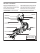
PART IDENTIFICATION CHART Use the drawings below to identify the small parts needed for assembly. The number in parentheses below each drawing is the key number of the part, from the PART LIST near the end of this manual. The number following the key number is the quantity needed for assembly. Note: If a part is not in the hardware kit, check to see if it has been preassembled. Extra parts may be included.
ASSEMBLY • Assembly requires two persons. • In addition to the included tool(s), assembly requires the following tools: • Place all parts in a cleared area and remove the packing materials. Do not dispose of the packing materials until you finish all assembly steps. one Phillips screwdriver one adjustable wrench • Left parts are marked “L” or “Left” and right parts are marked “R” or “Right.” Assembly may be easier if you have your own set of wrenches. To avoid damaging parts, do not use power tools.
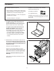
3. Orient the Rear Stabilizer Cover (2) as shown, and press it onto the Frame (1). 3 Attach the Rear Stabilizer Cover (2) with two M4 x 16mm Screws (104). 104 2 1 4. With the help of a second person, place some of the packing materials (not shown) under the front of the Frame (1). Have the second person hold the Frame to prevent it from tipping while you complete this step. 4 Identify the Right Front Stabilizer (6) and orient it as shown.
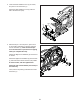
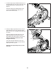
5. Orient the Front Stabilizer Cover (8) as shown, and route the Power Cord (not shown) over the top of the Front Stabilizer Cover. Then, press the Front Stabilizer Cover onto the Frame (1). 5 8 104 Attach the Front Stabilizer Cover (8) with two M4 x 16mm Screws (104). 1 6. Raise the Upright (4) to the vertical position. While a second person holds the Shield Cover (56) out of the way, secure the Upright with two M10 x 75mm Screws (142).
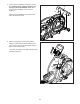
7. Locate the Right Upper Saddle Bracket (121) on the Right Roller Arm (45). Next, locate the Lower Saddle Bracket (26) on the right side of the elliptical. 7 Attach the Right Upper Saddle Bracket (121) to the Lower Saddle Bracket (26) with two M10 x 70mm Screws (139). 139 121 45 26 8. Identify the Right Upper Body Arm (61) and an Upper Body Arm Cover (77). Slide the Upper Body Arm Cover onto the Right Upper Body Arm as shown.
9. Attach the Tablet Holder (146) to the Console (7) with four #8 x 12mm Screws (147); start all the Screws, and then tighten them. 9 7 146 147 10. Make sure that all parts are properly tightened before you use the elliptical. Extra parts may be included. Place a mat beneath the elliptical to protect the floor.
THE CHEST HEART RATE MONITOR HOW TO PUT ON THE HEART RATE MONITOR • Store the heart rate monitor in a warm, dry place. Do not store the heart rate monitor in a plastic bag or other container that may trap moisture. If the heart rate monitor looks like the one shown in drawing 1, press the transmitter (A) onto the snap fasteners on the chest strap (B). If the heart rate monitor looks like the one shown in drawing 2, insert the tab (C) on one end of the chest strap (D) into one end of the transmitter (E).
HOW TO USE THE ELLIPTICAL HOW TO PLUG IN THE POWER CORD Follow the steps below to plug in the power cord. This product must be earthed. If it should malfunction or break down, earthing provides a path of least resistance for electric current to reduce the risk of electric shock. This product’s power cord has an equipment-earthing conductor and an earthing plug. IMPORTANT: If the power cord is damaged, it must be replaced with a manufacturer-recommended power cord. 1.
HOW TO MOVE THE ELLIPTICAL HOW TO LEVEL THE ELLIPTICAL Due to the size and weight of the elliptical, moving it requires two persons. Stand in front of the elliptical, hold the upright, and place one foot against one of the wheels. Have a second person lift the handle on the rear of the frame until the elliptical will roll on the wheels. Carefully move the elliptical to the desired location, and then lower it to the floor.
HOW TO EXERCISE ON THE ELLIPTICAL Upper Body Arm To mount the elliptical, hold the upper body arms or the handlebars and step onto the pedal that is in the lower position. Then, step onto the other pedal. Push the pedals until they begin to move with a continuous motion. Note: The crank arms can turn in either direction. It is recommended that you turn the crank arms in the direction shown by the arrow; however, for variety, you can turn the crank arms in the opposite direction.
CONSOLE DIAGRAM MAKE YOUR FITNESS GOALS A REALITY WITH IFIT.COM Upload your workout results to the iFit cloud and track your accomplishments. With your new iFit-compatible fitness equipment, you can use an array of features on iFit.com to make your fitness goals a reality: Set calorie, time, or distance goals for your workouts. Exercise anywhere in the world with customizable Google Maps. Watch high-definition videos with simulated workouts.
FEATURES OF THE CONSOLE HOW TO TURN ON THE POWER The advanced console offers an array of features designed to make your workouts more effective and enjoyable. IMPORTANT: If the elliptical has been exposed to cold temperatures, allow it to warm to room temperature before you turn on the power. If you do not do this, you may damage the console displays or other electrical components. The console features revolutionary iFit technology that enables the console to communicate with your wireless network.
HOW TO USE THE TOUCH SCREEN 2. Check for firmware updates. The console features a tablet with a full-color touch screen. The following information will help you become familiar with the tablet’s advanced technology: First, see step 1 on page 26 and step 2 on page 28 and select the maintenance mode. Then, see step 3 on page 28 and check for firmware updates. • The console functions similarly to other tablets.
HOW TO USE THE MANUAL MODE To vary the motion of the pedals, you can change the incline of the ramp. To change the incline, press one of the numbered 1 Step Ramp buttons on the console, press the Ramp increase and decrease buttons on the console, or press the Ramp increase and decrease buttons on the left handlebar. 1. Touch the screen or press any button on the console to turn on the console. See HOW TO TURN ON THE POWER on page 17. 2. Select the main menu.
5. Measure your heart rate if desired. If the display does not show your heart rate, make sure that your hands are positioned as described. Be careful not to move your hands excessively or to squeeze the contacts tightly. For optimal performance, clean the contacts using a soft cloth; never use alcohol, abrasives, or chemicals to clean the contacts. To use the chest heart rate monitor, see page 12. To use the handgrip heart rate monitor, follow the instructions below.
HOW TO USE AN ONBOARD WORKOUT 4. Start the workout. 1. Begin pedaling or press any button on the console to turn on the console. Touch the Start Workout button to start the workout. Each workout is divided into segments. One resistance level, one ramp incline level, and one target cadence (speed) are programmed for each segment. See HOW TO TURN ON THE POWER on page 17. 2. Select the main menu. During the workout, the profiles will show your progress.
If the resistance level and/or incline level for the current segment is too high or too low, you can manually override the setting by pressing the Resistance buttons or the Ramp buttons. If you press a Resistance button, you can then manually control the resistance (see step 3 on page 19). If you press a Ramp button, you can then manually control the incline (see step 3 on page 19). To return to the programmed resistance and/or incline settings of the workout, touch the Follow Workout button.
HOW TO USE A SET-A-GOAL WORKOUT manually override the setting by pressing the Resistance buttons or the Ramp buttons. If you press a Resistance button, you can then manually control the resistance (see step 3 on page 19). If you press a Ramp button, you can then manually control the incline (see step 3 on page 19). To return to the programmed resistance and/or incline settings of the workout, touch the Follow Workout button. 1. Begin pedaling or press any button on the console to turn on the console.
HOW TO USE AN IFIT WORKOUT To switch users within your iFit account, touch the user button at the bottom of the screen. If more than one user is associated with your iFit account, a list of users will appear. Touch the name of the desired user. To use an iFit workout, the console must be connected to a wireless network (see HOW TO USE THE WIRELESS NETWORK MODE on page 29). An iFit account is also required. 5. Select an iFit workout. 1. Add workouts to your schedule on iFit.com.
7. Follow your progress. 9. Turn on the fan if desired. See step 4 on page 19. The screen may also show a map of the route and a marker indicating your progress. Touch the buttons on the screen to select the desired map options. See step 6 on page 20. 10. When you are finished exercising, unplug the power cord. See step 7 on page 20. During a race or challenge, the screen will show your position in the race relative to other competitors. For more information about iFit features, go to iFit.
HOW TO USE THE EQUIPMENT SETTINGS MODE 6. Turn on or turn off the display demo mode. IMPORTANT: Some of the features described may not be enabled. Occasionally, a firmware update may cause your console to function slightly differently. 1. Select the settings main menu. The console features a display demo mode, designed to be used if the elliptical is displayed in a store. While the demo mode is turned on, the screen will show a preset presentation when the elliptical is not in use.
Note: If a passcode is enabled, the console will regularly ask for you to enter the passcode. The console will remain locked until the correct passcode is entered. IMPORTANT: If you forget your passcode, enter the following master passcode to unlock the console: 1985. 13. Select an update time. 10. Start the introductory slideshow. When you select an update time, you must also enable automatic console updates (see step 4).
HOW TO USE THE MAINTENANCE MODE 4. Calibrate the incline system. IMPORTANT: Some of the features described may not be enabled. Occasionally, a firmware update may cause your console to function slightly differently. Touch the Calibrate Incline button. Then, touch the Begin button to calibrate the incline system. The frame will automatically rise to the maximum incline level, lower to the minimum incline level, and then return to the starting position. This will calibrate the incline system.
HOW TO USE THE WIRELESS NETWORK MODE name (SSID). If your network has a password, you will also need to know the password. The console features a wireless network mode that allows you to set up a wireless network connection. An information box will ask if you want to connect to the wireless network. Touch the Connect button to connect to the network or touch the Cancel button to return to the list of networks. If the network has a password, touch the password entry box.
HOW TO USE THE SOUND SYSTEM HOW TO USE THE INTERNET BROWSER To play music or audio books through the console sound system while you exercise, plug a 3.5 mm male to 3.5 mm male audio cable (not included) into the jack on the console and into a jack on your personal audio player; make sure that the audio cable is fully plugged in. Note: To purchase an audio cable, see your local electronics store.
MAINTENANCE AND TROUBLESHOOTING MAINTENANCE HOW TO ADJUST THE REED SWITCH Regular maintenance is important for optimal performance and to reduce wear. Inspect and properly tighten all parts each time the elliptical is used. Replace any worn parts immediately. If the console does not display correct feedback, the reed switch should be adjusted. To adjust the reed switch, first unplug the power cord. Next, use a standard screwdriver and carefully pry the left Disc Cover (55) off the left Disc (71).
HOW TO ADJUST THE DRIVE BELT Then, look between the Left and Right Shields (73, 74) and locate the M8 Locknut (102). Tighten the Locknut until the Drive Belt (113) is tight. If the pedals slip while you are pedaling, even while the resistance is adjusted to the highest level, the drive belt may need to be adjusted. To adjust the drive belt, first unplug the power cord. Next, use a standard screwdriver and pry off the Shield Cover (56) and slide it upward.
EXERCISE GUIDELINES Burning Fat—To burn fat effectively, you must exercise at a low intensity level for a sustained period of time. During the first few minutes of exercise, your body uses carbohydrate calories for energy. Only after the first few minutes of exercise does your body begin to use stored fat calories for energy. If your goal is to burn fat, adjust the intensity of your exercise until your heart rate is near the lowest number in your training zone.
SUGGESTED STRETCHES The correct form for several basic stretches is shown at the right. Move slowly as you stretch; never bounce. 1. Toe Touch Stretch Stand with your knees bent slightly and slowly bend forward from your hips. Allow your back and shoulders to relax as you reach down toward your toes as far as possible. Hold for 15 counts, then relax. Repeat 3 times. Stretches: Hamstrings, back of knees and back. 1 2. Hamstring Stretch Sit with one leg extended.
NOTES 35
PART LIST Key No. Qty. 1 2 3 4 5 6 7 8 9 10 11 12 13 14 15 16 17 18 19 20 21 22 23 24 25 26 27 28 29 30 31 32 33 34 35 36 37 38 39 40 41 42 43 44 45 46 47 48 49 50 1 1 1 1 2 1 1 1 1 1 4 1 1 1 1 1 1 1 1 2 4 1 2 1 1 2 2 1 1 8 1 1 2 2 2 1 1 1 1 2 1 1 2 1 1 1 1 1 1 1 Model No. NTEVEL15017.0 R0417A Description Key No. Qty.
Key No. Qty. 101 102 103 104 105 106 107 108 109 110 111 112 113 114 115 116 117 118 119 120 121 122 123 124 125 126 127 1 7 2 82 1 1 4 4 6 1 1 1 1 1 1 2 4 2 2 2 1 1 1 4 1 1 1 Description Key No. Qty.
EXPLODED DRAWING A Model No. NTEVEL15017.
EXPLODED DRAWING B 130 42 40 148 19 110 83 93 86 114 130 86 102 43 28 102 43 18 Model No. NTEVEL15017.
ORDERING REPLACEMENT PARTS To order replacement parts, please see the front cover of this manual.