Model No. NETL12807.2 Serial No. Write the serial number in the space above for reference. USER'S MANUAL Serial Number Decal QUESTIONS? If you have questions, or if there are missing parts, please contact us: Call: 08457 089 009 From Ireland: 053 92 36102 E-mail: www.iconsupport.eu Write: ICON Health & Fitness, Ltd. c/o HI Group PLC, Express Way Whitwood, West Yorkshire WF10 5QJ UK CAUTION Read all precautions and instructions in this manual before using this equipment.
TABLE OF CONTENTS WARNING DECAL PLACEMENT . . . . . . . . . . . . . . . . . . . . . . . . . . . . . . . . . . . . . . . . . . . . . . . . . . . . . . . . . . . . . .2 IMPORTANT PRECAUTIONS . . . . . . . . . . . . . . . . . . . . . . . . . . . . . . . . . . . . . . . . . . . . . . . . . . . . . . . . . . . . . . . .3 BEFORE YOU BEGIN . . . . . . . . . . . . . . . . . . . . . . . . . . . . . . . . . . . . . . . . . . . . . . . . . . . . . . . . . . . . . . . . . . . . . .5 ASSEMBLY . . . . . . . . . . . . .
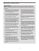
IMPORTANT PRECAUTIONS WARNING: To reduce the risk of serious injury, read all important precautions and instructions in this manual and all warnings on your treadmill before using your treadmill. ICON assumes no responsibility for personal injury or property damage sustained by or through the use of this product. 1. Before beginning any exercise program, consult your physician. This is especially important for persons over age 35 or persons with pre-existing health problems. 11.
19. Never leave the treadmill unattended while it is running. Always remove the key, unplug the power cord, and switch the reset/off circuit breaker to the off position when the treadmill is not in use. (See the drawing on page 5 for the location of the circuit breaker.) 24. 20. Do not attempt to raise, lower, or move the treadmill until it is properly assembled. (See ASSEMBLY on page 6, and HOW TO FOLD AND MOVE THE TREADMILL on page 20.) You must be able to safely lift 45 lbs.
BEFORE YOU BEGIN Thank you for selecting the revolutionary NordicTrack® C2000 treadmill. The C2000 treadmill offers a selection of features designed to make your workouts at home more enjoyable and effective. And when youʼre not exercising, the unique C2000 treadmill can be folded up, requiring less than half the floor space of other treadmills. ing this manual, please see the front cover of this manual. To help us assist you, note the product model number and serial number before contacting us.
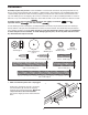
ASSEMBLY Assembly requires two persons. Set the treadmill in a cleared area and remove all packing materials. Do not dispose of the packing materials until assembly is completed. Note: The underside of the treadmill walking belt is coated with high-performance lubricant. During shipping, a small amount of lubricant may be transferred to the top of the walking belt or the shipping carton. This is normal and does not affect treadmill performance.
2. With the help of a second person, carefully tip the treadmill onto its left side. Partially fold the Frame (56) so that the treadmill is more stable; do not fully fold the Frame yet. 2 38 Cut the ties securing the Upright Wire (38) to the Base (83). Locate the tie in the indicated hole in the Base, and use the tie to pull the Upright Wire out of the hole. 83 Hole 81 2 Attach a Base Pad (81) to the Base (83) in the location shown with a Base Pad Spacer (13) and a #8 x 1" Tek Screw (2).
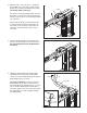
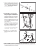
5. Set the Right Upright Spacer (79) on the Base (83). Be careful not to pinch the Upright Wire (38). With the help of a second person, insert two 3/8" x 5" Bolts (6) with two 3/8" Star Washers (9) into the Right Upright (78), and set the Right Upright into the Right Upright Spacer. If necessary, use a rubber mallet on top of the Right Upright to make sure that the Upright is fully inserted into the Right Upright Spacer. 5 78 Finger tighten the 3/8" x 5" Bolts (6); do not fully tighten the Bolts yet.
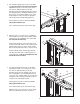
8. Set the console assembly face down on a soft surface to avoid scratching the console assembly. Hold the Right Handrail (95) near the console assembly. Next, insert the console wire into the large hole in the Right Handrail and out of the top as shown. If necessary, use needlenose pliers to help pull the console wire out. 8 Console Wire Hole 1 95 1 Attach the Right Handrail (95) and the Left Handrail (not shown) with four #8 x 3/4" Screws (1) (two are shown). Make sure that no wires are pinched.
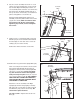
11. Identify the Storage Latch (53). Remove the tie from the end of the tube. Make sure that the sleeve has been slid over the indicated hole and that the Latch Knob (54) is locked into the indicated hole. Pull on the sleeve to make sure that it is locked into place. 11 54 Tube 12. Raise the Frame (56) to the position shown. Have a second person hold the Frame until this step is completed.
HOW TO USE THE CHEST PULSE SENSOR HOW TO PUT ON THE CHEST PULSE SENSOR • Store the chest pulse sensor in a warm, dry place. Do not store the chest pulse sensor in a plastic bag or other container that may trap moisture. The chest pulse sensor consists of two components: the chest strap and the sensor unit (see the drawing below). Insert the tab on one end of the chest strap into the hole in one end of the sensor unit, as shown in the inset drawing.
OPERATION AND ADJUSTMENT THE PRE-LUBRICATED WALKING BELT Your treadmill features a walking belt coated with high-performance lubricant. IMPORTANT: Never apply silicone spray or other substances to the walking belt or the walking platform. Such substances will deteriorate the walking belt and cause excessive wear. HOW TO PLUG IN THE POWER CORD This product must be earthed.
CONSOLE DIAGRAM Navigation Buttons FEATURES OF THE CONSOLE The treadmill console offers an impressive array of features designed to help you get the most from your workouts. When the manual mode of the console is selected, the speed and incline of the treadmill can be changed with the touch of a button. As you exercise, the console will display continuous exercise feedback. You can even measure your heart rate using the builtin handgrip pulse sensor or the chest pulse sensor.
HOW TO TURN ON THE POWER IMPORTANT: If the treadmill has been exposed to cold temperatures, allow it to warm to room temperature before turning on the power. If you do not do this, the console displays or other electrical components may become damaged. Plug in the power cord (see page 12). Next, locate the reset/off circuit breaker on the treadmill frame near the power cord. Switch the circuit breaker to the reset position. HOW TO USE THE MANUAL MODE 1. Insert the key into the console.
4. Change the incline of the treadmill as desired. • Your heart rate. Note: Your heart rate can be displayed only while you use the handgrip pulse sensor or the chest pulse sensor. To change the incline of the treadmill, press the Incline increase and decrease buttons. Each time you press the Incline increase or decrease button, the incline will change by 0.5%. To change the incline quickly, press one of the incline buttons numbered 0 through 12.
6. Measure your heart rate if desired. 7. Turn on the fan if desired. Note: If you use the handgrip pulse sensor and the chest pulse sensor at the same time, the console will not display your heart rate accurately. See page 11 for more information on the chest pulse sensor. Before using the handgrip pulse sensor, remove the clear plastic film from the metal contacts. In addition, make sure that your hands are clean. The fan features low, high, and auto speed settings.
HOW TO USE A PRESET WORKOUT A profile of the speed settings of the workout will appear in the display. A small arrow below the profile will indicate your progress. 1. Insert the key into the console. See HOW TO TURN ON THE POWER on page 14. 2. Select one of the preset workouts. To select a weight loss workout or a performance workout, press the Weight Loss Workouts button or the Performance Workouts button repeatedly. Profiles of the speed settings of the workouts will appear in the display.
HOW TO USE AN IFIT CARD During the workout, a personal trainer will guide you through the workout. You can select an audio setting for your personal trainer (see THE INFORMATION MODE on page 19). 1. Insert the key into the console. See HOW TO TURN ON THE POWER on page 14.
HOW TO USE THE STEREO SOUND SYSTEM This product has been designed specifically to work with iPod and has been certified by the developer to meet Apple performance standards. To play music or audio books through the consoleʼs stereo speakers, you must connect your iPod, MP3 player, CD player, or other personal audio player to the console through the audio jack or through the Compatible Music Port for iPod. The music port will charge your iPod while you use it.
HOW TO ADJUST THE CUSHIONING SYSTEM Remove the key from the console and unplug the power cord. The treadmill features a cushioning system that reduces the impact as you walk or run on the treadmill. To increase the firmness of the walking platform, step off the treadmill and slide the platform cushions toward the front of the treadmill. To decrease the firmness, step off the treadmill and slide the platform cushions toward the back of the treadmill.
HOW TO MOVE THE TREADMILL Before moving the treadmill, convert the treadmill to the storage position as described above. Make sure that the latch knob is locked in the storage position. 1. Hold a handrail and the frame and place one foot against one of the wheels. Frame Handrail 2. Tip the treadmill back until it rolls freely on the wheels. Carefully move the treadmill to the desired location. Never move the treadmill without tipping it back.
TROUBLESHOOTING Most treadmill problems can be solved by following the steps below. Find the symptom that applies, and follow the steps listed. If further assistance is needed, please see the front cover of this manual. PROBLEM: The power does not turn on SOLUTION: a. Make sure that the power cord is plugged into a properly earthed outlet. (See page 12.) If an extension cord is needed, use only a 3-conductor, 1 mm2 (14-gauge) cord that is no longer than 1.5 m (5 ft.). b.
Remove the three #8 x 3/4" Screws (1) and carefully pivot the Hood (61) off. 61 Locate the Reed Switch (71) and the Magnet (50) on the left side of the Pulley (51). Turn the Pulley until the Magnet is aligned with the Reed Switch. Make sure that the gap between the Magnet and the Reed Switch is about 1/8 in. (3 mm). If necessary, loosen the 3/4" Reed Switch Screw (15), move the Reed Switch slightly, and then retighten the Screw. Reattach the Hood (not shown).
PROBLEM: The walking belt is off-center or slips when walked on SOLUTION: a. If the walking belt is off-center, first remove the key and UNPLUG THE POWER CORD. If the walking belt has shifted to the left, use the hex key to turn the left rear roller bolt clockwise 1/2 of a turn; if the walking belt has shifted to the right, turn the bolt counterclockwise 1/2 of a turn. Be careful not to overtighten the walking belt. Then, plug in the power cord, insert the key, and run the treadmill for a few minutes.
EXERCISE GUIDELINES WARNING: Before beginning this Burning Fat—To burn fat effectively, you must exercise at a low intensity level for a sustained period of time. During the first few minutes of exercise, your body uses carbohydrate calories for energy. Only after the first few minutes of exercise does your body begin to use stored fat calories for energy. If your goal is to burn fat, adjust the intensity of your exercise until your heart rate is near the lowest number in your training zone.
PART LIST—Model No. NETL12807.2 To locate the parts listed below, see the EXPLODED DRAWING near the end of this manual. Key No. Qty. 1 2 3 4 5 6 7 8 9 10 11 12 13 14 15 16 17 18 19 20 21 22 23 24 25 26 27 28 29 30 31 32 33 34 35 36 37 38 39 40 41 42 43 44 45 46 47 48 49 50 25 4 1 6 2 4 4 8 4 4 5 12 2 1 1 10 2 2 2 2 1 1 2 2 10 2 2 1 4 2 2 1 2 4 1 2 3 1 1 2 1 1 2 1 1 2 2 2 1 1 Description Key No. Qty.
Key No. Qty. 101 102 103 104 105 106 107 108 109 110 111 112 113 1 1 1 1 2 1 1 1 1 1 1 1 1 Description Key No. Qty.
20 31 25 30 57 12 59 36 58 3 20 16 18 42 34 102 16 25 41 31 60 30 25 12 44 18 43 16 27 47 34 46 57 36 29 40 24 107 12 45 25 25 16 16 17 8 55 48 51 43 4 54 47 27 16 25 50 56 53 29 25 17 46 40 24 49 25 8 48 111 4 EXPLODED DRAWING A—Model No. NETL12807.
EXPLODED DRAWING B—Model No. NETL12807.
EXPLODED DRAWING C—Model No. NETL12807.
EXPLODED DRAWING D—Model No. NETL12807.
ORDERING REPLACEMENT PARTS To order replacement parts, please see the front cover of this manual.