www.nordictrack.com Model No. NTEL18913C.0 Serial No. Write the serial number in the space above for reference. Serial Number Decal ACTIVATE YOUR WARRANTY To register your product and activate your warranty today, contact Customer Service. CUSTOMER SERVICE Call toll-free 1-888-936-4266 Mon.–Fri. 7:30 a.m.–4:30 p.m. ET (excluding holidays) or email us at customerservice@iconcanada.ca Please do not contact the store. CAUTION Read all precautions and instructions in this manual before using this equipment.
TABLE OF CONTENTS WARNING DECAL PLACEMENT . . . . . . . . . . . . . . . . . . . . . . . . . . . . . . . . . . . . . . . . . . . . . . . . . . . . . . . . . . . . . . .2 IMPORTANT PRECAUTIONS . . . . . . . . . . . . . . . . . . . . . . . . . . . . . . . . . . . . . . . . . . . . . . . . . . . . . . . . . . . . . . . . . . 3 BEFORE YOU BEGIN. . . . . . . . . . . . . . . . . . . . . . . . . . . . . . . . . . . . . . . . . . . . . . . . . . . . . . . . . . . . . . . . . . . . . . . .
IMPORTANT PRECAUTIONS WARNING: To reduce the risk of burns, fire, electric shock, or injury to persons, read all important precautions and instructions in this manual and all warnings on your elliptical before using your elliptical. ICON assumes no responsibility for personal injury or property damage sustained by or through the use of this product. 1. It is the responsibility of the owner to ensure that all users of the elliptical are adequately informed of all precautions. 12. 2.
BEFORE YOU BEGIN Thank you for selecting the revolutionary NORDICTRACK® E 11.7 elliptical. The E 11.7 elliptical provides an impressive selection of features designed to make your workouts at home more effective and enjoyable. reading this manual, please see the front cover of this manual. To help us assist you, note the product model number and serial number before contacting us. The model number and the location of the serial number decal are shown on the front cover of this manual.
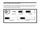
PART IDENTIFICATION CHART Use the drawings below to identify the small parts needed for assembly. The number in parentheses below each drawing is the key number of the part, from the PART LIST near the end of this manual. The number following the key number is the quantity needed for assembly. Note: If a part is not in the hardware kit, check to see if it has been preassembled. Extra parts may be included.
ASSEMBLY • Assembly requires two persons. • In addition to the included tool(s), assembly requires the following tools: • Place all parts in a cleared area and remove the packing materials. Do not dispose of the packing materials until you complete all assembly steps. one Phillips screwdriver one adjustable wrench • Left parts are marked “L” or “Left” and right parts are marked “R” or “Right.” Assembly may be easier if you have your own set of wrenches. To avoid damaging parts, do not use power tools.
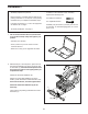
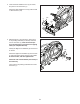
3. Orient the Rear Stabilizer Cover (2) as shown, and press it onto the Frame (1). 3 Attach the Rear Stabilizer Cover (2) with two M4 x 16mm Screws (104). 2 104 104 1 4. With the help of a second person, place some of the packing materials (not shown) under the front of the Frame (1). Have the second person hold the Frame to prevent it from tipping while you complete this step. 4 Identify the Right Front Stabilizer (6) and orient it as shown.
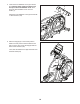
5. Orient the Front Stabilizer Cover (8) as shown, and route the Power Cord (not shown) over the top of the Front Stabilizer Cover. Then, press the Front Stabilizer Cover onto the Frame (1). 5 8 104 Attach the Front Stabilizer Cover (8) with two M4 x 16mm Screws (104). 1 6. Raise the Upright (4) to the vertical position. While a second person holds the Shield Cover (56) out of the way, secure the Upright with two M10 x 75mm Screws (142).
7. Locate the Right Upper Saddle Bracket (121) on the Right Roller Arm (45). Next, locate the Lower Saddle Bracket (26) on the right side of the elliptical. 7 Attach the Right Upper Saddle Bracket (121) to the Lower Saddle Bracket (26) with two M10 x 70mm Screws (139). 139 121 45 26 8. Identify the Right Upper Body Arm (61) and an Upper Body Arm Cover (77). Slide the Upper Body Arm Cover onto the Right Upper Body Arm as shown.
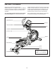
THE CHEST HEART RATE MONITOR HOW TO PUT ON THE HEART RATE MONITOR The heart rate monitor consists of a chest strap and a sensor. Insert the tab on one end of the chest strap into the hole in one end of the sensor as shown. Then, press the end of the sensor under the buckle on the chest strap. The tab should be flush with the front of the sensor.
HOW TO USE THE ELLIPTICAL HOW TO PLUG IN THE POWER CORD A temporary adapter may be used to connect the power cord to a 2-pole receptacle as shown at the right if a properly grounded outlet is not available. This product must be grounded. If it should malfunction or break down, grounding provides a path of least resistance for electric current to reduce the risk of electric shock. The power cord has a plug with a grounding pin.
HOW TO MOVE THE ELLIPTICAL HOW TO EXERCISE ON THE ELLIPTICAL Due to the size and weight of the elliptical, moving it requires two persons. Stand in front of the elliptical, hold the upright, and place one foot against one of the wheels. Have a second person lift the handle on the rear of the frame until the elliptical will roll on the wheels. Carefully move the elliptical to the desired location, and then lower it to the floor.
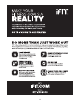
CONSOLE DIAGRAM MAKE YOUR FITNESS GOALS A REALITY WITH IFIT.COM Upload your workout results to the iFit cloud and track your accomplishments. With your new iFit-compatible fitness equipment, you can use an array of features on iFit.com to make your fitness goals a reality: Set calorie, time, or distance goals for your workouts. Exercise anywhere in the world with customizable Google Maps.
FEATURES OF THE CONSOLE HOW TO TURN ON THE POWER The advanced console offers an array of features designed to make your workouts more effective and enjoyable. IMPORTANT: If the elliptical has been exposed to cold temperatures, allow it to warm to room temperature before you turn on the power. If you do not do this, you may damage the console displays or other electrical components. When you use the manual mode of the console, you can change the resistance of the pedals with the touch of a button.
HOW TO USE THE MANUAL MODE Calories—This display mode will show the approximate number of calories you have burned. 1. Begin pedaling or press any button on the console to turn on the console. Calories per Hour (Calories/Hr)—This display mode will show the approximate number of calories you are burning per hour. See HOW TO TURN ON THE POWER on page 16. Distance (Dist.)—This display mode will show the distance that you have pedaled in miles or kilometers. 2. Select the manual mode.
As you exercise, the workout intensity level bar will indicate the approximate intensity level of your exercise. When your pulse is detected, a heart symbol will flash in the display each time your heart beats, one or two dashes will appear, and then your heart rate will be shown. For the most accurate heart rate reading, hold the contacts for at least 15 seconds. If the display does not show your heart rate, make sure that your hands are positioned as described.
HOW TO USE AN ONBOARD WORKOUT the profile will begin to flash. If a different resistance level, ramp incline level, and/or target rpm is programmed for the next segment, the resistance level, ramp incline level, and/or target rpm will appear in the display for a few seconds to alert you. The resistance of the pedals and the incline level of the ramp will then change. 1. Begin pedaling or press any button on the console to turn on the console. See HOW TO TURN ON THE POWER on page 16. 2.
HOW TO USE A SET-A-GOAL WORKOUT Note: The calorie goal is an estimate of the number of calories that you will burn during the workout. The actual number of calories that you burn will depend on various factors such as your weight. In addition, if you manually change the resistance level or the ramp incline level during the workout, the number of calories you burn will be affected. 1. Begin pedaling or press any button on the console to turn on the console. See HOW TO TURN ON THE POWER on page 16. 2.
HOW TO USE AN IFIT WORKOUT Press the Map button, the Train button, or the Lose Wt. button to download the next workout of that type in your schedule. You must have an iFit module to use an iFit workout. To purchase an iFit module at any time, go to www.iFit.com or call the telephone number on the front cover of this manual. Press the Compete button to compete in a race that you have previously scheduled.
6. Follow your progress with the display. 7. Measure your heart rate if desired. See step 4 on page 17. See step 5 on page 18. The My Trail tab will show a map of the trail you are walking or running or it will show a track and the number of laps you complete. 8. Turn on the fan if desired. During a competition workout, the Competition tab will show your progress in the race. As you race, the top line in the matrix will show how much of the race you have completed.
HOW TO CHANGE CONSOLE SETTINGS Ramp increase and decrease buttons to adjust the contrast level. 1. Select the settings mode. The following additional settings will be available if an iFit module is inserted into the console. To select the settings mode, press the Settings button. Trainer Voice—The currently selected setting for the audio coach will appear in the display. Press the Enter button repeatedly to turn the audio coach ON or OFF.
MAINTENANCE AND TROUBLESHOOTING MAINTENANCE When the ramp stops moving, the ramp is calibrated. Then, press the Calorie Workouts button repeatedly to exit the calibration mode. Inspect and tighten all parts of the elliptical regularly. Replace any worn parts immediately. HOW TO ADJUST THE REED SWITCH To clean the elliptical, use a damp cloth and a small amount of mild soap. IMPORTANT: To avoid damage to the console, keep liquids away from the console and keep the console out of direct sunlight.
HOW TO ADJUST THE DRIVE BELT Then, look between the Shields (73, 74) and locate the M8 Locknut (102). Tighten the Locknut until the Drive Belt (113) is tight. If the pedals slip while you are pedaling, even while the resistance is adjusted to the highest level, the drive belt may need to be adjusted. To adjust the drive belt, first unplug the power cord. Next, use a flat screwdriver and pry off the Shield Cover (56) and slide it upward.
EXERCISE GUIDELINES Burning Fat—To burn fat effectively, you must exercise at a low intensity level for a sustained period of time. During the first few minutes of exercise, your body uses carbohydrate calories for energy. Only after the first few minutes of exercise does your body begin to use stored fat calories for energy. If your goal is to burn fat, adjust the intensity of your exercise until your heart rate is near the lowest number in your training zone.
SUGGESTED STRETCHES The correct form for several basic stretches is shown at the right. Move slowly as you stretch; never bounce. 1. Toe Touch Stretch Stand with your knees bent slightly and slowly bend forward from your hips. Allow your back and shoulders to relax as you reach down toward your toes as far as possible. Hold for 15 counts, then relax. Repeat 3 times. Stretches: Hamstrings, back of knees and back. 1 2. Hamstring Stretch Sit with one leg extended.
PART LIST Key No. Qty. 1 2 3 4 5 6 7 8 9 10 11 12 13 14 15 16 17 18 19 20 21 22 23 24 25 26 27 28 29 30 31 32 33 34 35 36 37 38 39 40 41 42 43 44 45 46 47 48 49 50 1 1 1 1 2 1 1 1 1 1 2 1 1 1 1 1 1 1 1 2 4 1 1 2 1 2 2 1 1 8 1 2 2 2 2 1 1 1 1 2 1 1 2 1 1 1 1 1 1 1 Model No. NTEL18913C.0 R0714B Description Key No. Qty.
Key No. Qty. 101 102 103 104 105 106 107 108 109 110 111 112 113 114 115 116 117 118 119 120 121 122 123 124 125 126 127 128 129 130 131 1 7 2 80 1 1 4 1 1 1 1 1 1 1 1 1 4 2 2 2 1 1 1 4 1 1 1 2 4 4 2 Description Key No. Qty.
EXPLODED DRAWING A Model No. NTEL18913C.
EXPLODED DRAWING B 130 42 40 102 28 93 86 23 130 113 102 22 101 100 139 117 121 141 104 118 78 104 128 149 50 104 30 104 70 124 70 99 49 150 152 136 94 87 103 58 82 55 30 119 35 104 151 31 126 152 35 21 53 120 125 137 138 64 36 84 79 133 138 71 95 95 143 77 133 98 104 96 111 104 95 99 129 132 57 132 104 149 30 41 61 149 104 98 26 51 149 131 60 45 51 109 74 20 117 99 30 57 114 112 86 43 81 102 110 108 147 145 19 83
ORDERING REPLACEMENT PARTS To order replacement parts, please see the front cover of this manual.