
Datasheet


Revision 1.5 Page 27 of 41
nRF905 Product Specification
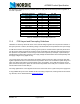
10.3 ShockBurst™ RX timing
Figure 10. Timing diagram for standby to receiving
After the Data Ready (DR) has been set high a valid data packet is available in the RX data register. This
may be clocked out in RX mode or standby mode. After the data has been clocked out through the SPI the
Data Ready (DR) and Address Match (AM) pins are reset to low.
The RX register is reset if the PWR_UP pin is taken low or if the device is switched into TX mode, that is,
TXEN is taken high. This also results in the Data Ready (DR) and Address Match (AM) pins being reset to
low.
10.4 Preamble
In each data packet transmitted by the nRF905 a preamble is added automatically. The preamble is a pre-
defined bit sequence used to adjust the receiver for optimal performance. A ten bit sequence is used as
preamble in nRF905. The length of the preamble, t
preamble
, is then 200µs.
10.5 Time On Air
The time on air is the sum of the radio start up time and the data packet length. The length of the preamble,
address field, payload and CRC checksum give the data packet length while the radio start up time is given
in Table 11. While preamble length and start up time are fixed the user sets the other parameters in the RF
configuration register. The below equation shows how to calculate TOA:
t
startup
and t
preamble
are RF start up time and preamble time respectively. N
address
, N
payload
and N
CRC
are
numbers of bits in the address, payload and CRC checksum while BR is the bitrate, which is equal to
50kbps.
PWR_UP
TX_EN
TRX_CE
RX DATA
TIME
AM
DR
CD
T0 = Receiver Enabled -Listening for Data
T1 = Carrier Detect finds a carrier
T2 = AM - Correct Address Found
T3 = DR - Data packet with correct Address/CRC
650uS to enter RX
mode from
TRX_CE being set
high.
T0 T1 T2 T3
650uS
BR
NNN
ttTOA
CRCpayloadaddress
preamblestartup
++
++=