
Datasheet


Revision 1.5 Page 21 of 41
nRF905 Product Specification
9.2 SPI Instruction Set
The available commands used on the SPI are shown below. Whenever CSN is set low the interface
expects an instruction. Every new instruction must be started by a high to low transition on CSN.
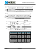
Table 13. Instruction set for the nRF905 SPI.
A read or a write operation may operate on a single byte or on a set of succeeding bytes from a given start
address defined by the instruction. When accessing succeeding bytes, you read or write the MSB of the
byte with the smallest byte number first.
9.3 SPI Timing
The interface supports SPI mode 0. SPI operation and timing is given in Figure 6. to Figure 8. and in Table
14.. The device must be in one of the power saving modes for you to read or write to the configuration reg-
isters.
Instruction set for the nRF905 SPI
Instruction
Name
Instruction
Format
Operation
W_CONFIG
(WC)
0000 AAAA Write Configuration register. AAAA indicates which byte the
write operation is to be started from. Number of bytes
depends on start address AAAA.
R_CONFIG
(RC)
0001 AAAA Read Configuration register. AAAA indicates which byte the
read operation is to be started from. Number of bytes
depends on start address AAAA.
W_TX_PAYLO
AD
(WTP)
0010 0000 Write TX-payload: 1 – 32 bytes. A write operation always
starts at byte 0.
R_TX_PAYLO
AD
(RTP)
0010 0001 Read TX-payload: 1 – 32 bytes. A read operation always
starts at byte 0.
W_TX_ADDRE
SS
(WTA)
0010 0010 Write TX-address: 1 – 4 bytes. A write operation always
starts at byte 0.
R_TX_ADDRE
SS
(RTA)
0010 0011 Read TX-address: 1 – 4 bytes. A read operation always
starst at byte 0
R_RX_PAYLO
AD
(RRP)
0010 0100 Read RX-payload: 1 – 32 bytes. A read operation always
starts at byte 0.
CHANNEL_CO
NFIG
(CC)
1000 pphc
cccc cccc
Special command for fast setting of CH_NO, HFREQ_PLL
and PA_PWR in the CONFIGURATION REGISTER.
CH_NO= ccccccccc, HFREQ_PLL = h PA_PWR = pp
STATUS REG-
ISTER
N.A. The content of the status register (S[7:0]) is always read to
MISO after a high to low transition on CSN as shown in Fig-
ure 6. and Figure 7.