
Datasheet


Revision 1.5 Page 20 of 41
nRF905 Product Specification
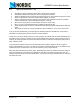
9 Device Configuration
All configuration of the nRF905 is through the SPI. The interface consists of five registers. A SPI instruction
set is used to decide which operation shall be performed. The SPI can be activated in any mode however,
we recommend that the chip is in standby or power down mode.
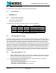
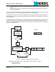
9.1 SPI Register Configuration
The SPI consists of five internal registers. A register readback mode is implemented to allow verification of
the register contents.
Figure 5. SPI – interface and the five internal registers.
Table 12. Internal registers description
Internal registers Description
Status – Register Register contains status of Data Ready (DR), Address Match (AM).
RF – Configuration Register Register contains transceiver setup information such as frequency and
output power ext.
TX – Address Register contains address of target device. How many bytes used is set
in the configuration register.
TX – Payload Register containing the payload information to be sent in a Shock-
Burst™ packet. How many bytes used is set in the configuration regis-
ter.
RX – Payload Register containing the payload information derived from a received
valid ShockBurst
™ packet. How many bytes used is set in the configu-
ration register. Valid data in the RX-Payload register is indicated with a
high Date Ready (DR) signal.
TX-PAYLOAD
EN
DTA
CLK
I/O-reg
CSN
MOSI
MISO
SCK
RF - CONFIGURATION
REGISTER
EN
DTA
CLK
TX-ADDRESS
EN
DTA
CLK
RX-PAYLOAD
EN
DTA
CLK
STATUS-REGISTER
EN
DTA
CLK