
Datasheet


Revision 1.5 Page 18 of 41
nRF905 Product Specification
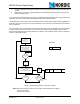
8.5 Typical ShockBurst™ RX
1. ShockBurst™ RX is selected by setting TRX_CE high and TX_EN low.
2. After 650µs nRF905 is monitoring the air for incoming communication.
3. When the nRF905 senses a carrier at the receiving frequency, Carrier Detect (CD) pin is set high.
4. When a valid address is received, Address Match (AM) pin is set high.
5. When a valid packet has been received (correct CRC found), nRF905 removes the preamble,
address and CRC bits, and the Data Ready (DR) pin is set high.
6. MCU sets the TRX_CE low to enter standby mode (low current mode).
7. MCU can clock out the payload data at a suitable rate through the SPI.
8. When all payload data is retrieved, nRF905 sets Data Ready (DR) and Address Match (AM) low
again.
9. The chip is now ready for entering ShockBurst™ RX, ShockBurst™ TX or, power down mode.
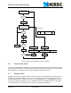
If TX_EN is set high while TRX_CE is kept high, the nRF905 would enter ShockBurst™ TX and start a
transmission according to the present contents in the SPI registers.
If TRX_CE or TX_EN is changed during an incoming packet, the nRF905 changes mode immediately and
the packet is lost. However, if the MCU is sensing the Address Match (AM) pin, it knows when the chip is
receiving an incoming packet and can therefore decide whether to wait for the Data Ready (DR) signal or
enter a different mode.
To avoid spurious address matches it is recommended that the address length be 24 bits or higher in
length. Small addresses such as 8 or 16 bits can often lead to statistical failures due to the address being
repeated as part of the data packet. This can be avoided by using a longer address.
Each byte within the address should be unique. Repeating bytes within the address reduces the effective-
ness of the address and increases its susceptibility to noise which increases the packet error rate. The
address should also have several level shifts (that is, 10101100) reducing the statistical effect of noise and
the packet error rate.