
Datasheet


Revision 1.5 Page 11 of 41
nRF905 Product Specification
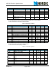
Table 6. General RF conditions
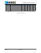
Table 7. Transmitter operation
Symbol Parameter (condition) Notes Min. Typ. Max. Units
f
OP
Operating frequency
a
a. Operates in the 433, 868 and 915MHz ISM band.
430 928 MHz
f
XTAL
Crystal frequency
b
b. The crystal frequency may be chosen from 5 different values (4, 8, 12, 16, and 20MHz).
420MHz
Δf Frequency deviation ±42 ±50 ±58 kHz
BR Data rate
c
c. Data is Manchester encoded before GFSK modulation.
50 kbps
f
CH433
Channel spacing for 433MHz
band
100 kHz
f
CH868/915
Channel spacing for 868/
915MHz band
200 kHz
Symbol Parameter (condition) Notes Min. Typ. Max. Units
P
RF10
Output power 10dBm setting
a
a. Optimum load impedance, please see peripheral RF information.
710 11dBm
P
RF6
Output power 6dBm setting
a
36 9dBm
P
RF-2
Output power –2dBm setting
a
-6 -2 2 dBm
P
RF-10
Output power -10dBm setting
a
-14 -10 -6 dBm
P
BW_-16
-16dBc bandwidth for modulated carrier
b
b. Data is Manchester encoded before GFSK modulation.
173 kHz
P
BW_-24
-24dBc bandwidth for modulated carrier
b
222 kHz
P
BW_-32
-32dBc bandwidth for modulated carrier
b
238 kHz
P
BW_-36
-36dBc bandwidth for modulated carrier
b
313 kHz
P
RF1
1
st
adjacent channel transmit power
c
c. Channel width and channel spacing is 200kHz.
-27 dBc
P
RF2
2
nd
adjacent channel transmit power
c
-54 dBc
I
TX10dBm
Supply current @ 10dBm output power 30 mA
I
TX-10dBm
Supply current @ -10dBm output power 9 mA
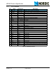
Symbol Parameter (condition) Notes Min. Typ. Max. Units
I
RX
Supply current in receive mode 12.5 mA
RX
SENS
Sensitivity at 0.1%BER -100 dBm
RX
MAX
Maximum received signal 0 dBm
C/I
CO
C/I Co-channel
a
13 dB
C/I
1ST
1
st
adjacent channel selectivity C/I
200kHz
a
-7 dB
C/I
2ND
2
nd
adjacent channel selectivity C/I
400kHz
a
-16 dB
C/I
+1M
Blocking at +1MHz
a
-40 dB
C/I
-1M
Blocking at -1MHz
a
-50 dB
C/I
-2M
Blocking at -2MHz
a
-63 dB