Intelligent Drivesystems, Worldwide Services GB B2000 Operating and Installation Instructions for Explosion Protected Gear Units and Geared Motors
Contents 1 1.1 1.2 1.3 1.4 1.5 Notes ...................................................................................................................... 4 General information ............................................................................................... 4 Safety and information symbols............................................................................. 4 Correct use ............................................................................................................
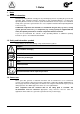
1. Notes 1 Notes 1.1 General information Read the Operating Manual carefully prior to performing any work on or putting the gear unit into operation. Strict compliance with the instructions in this Operating Manual is essential. This Operating Manual and all associated special documentation must be kept in the immediate vicinity of the gear unit. If geared motors are used, compliance with the Motor Operating Manual is also necessary.
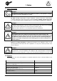
1. Notes 1.4 Safety information Danger! No explosive atmosphere may be present during any work e.g. transportation, storage, electrical connection, maintenance or repair. All work including transportation, storage, installation, electrical connection, commissioning, servicing, maintenance and repair must be performed only by qualified specialist personnel. It is recommended that repairs to NORD Products are carried out by the NORD Service department.
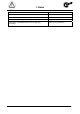
1. Notes Coupling components Plastic with steel Flat seals Asbestos-free sealing material Gear oil Additive mineral oil Synthetic gear oil (Rating plate labelling: CLP PG) Polyglycol-based lubricants Cooling spiral, embedding material of the cooling spiral, screw fittings Copper, epoxy, yellow brass -6- B2000-GB-0413 www.nord.
2. Description of gear units 2 Description of gear units 2.1 Type designations and gear unit types Helical gear units Type designations: SK 11E, SK 21E, ..... SK 51E (single-stage) SK 02, SK 12, ........
2. Description of gear units NORDBLOC helical gear units Type designations: SK 320, SK 172, SK 272, ..... SK 972 (2-stage) SK 273, SK 373, ..... SK 973 (3-stage) SK 072.1, SK 172.1 (2-stage) SK 372.1, …. SK 672.1 (2-stage) SK 373.1, …. SK 673.1 (3-stage) SK 772.1, SK 872.1, SK 972.1 (2-stage) SK 773.1, SK 873.1, SK 973.
2. Description of gear units Parallel shaft gear units Type designations: SK 0182NB, SK 0282NB, SK 1282, ..... SK 9282, SK 10282, SK 11282 (2-stage) SK 1382NB, SK 2382, ….. SK 9382, SK 10382, SK 11382, SK 12382 (3-stage) www.nord.
2. Description of gear units Bevel gear units Type designations: SK 92072, SK 92172, SK 92372, SK 92672, SK 92772 SK 92072.1, SK 92172.1, SK 92372.1, SK 92672.1, SK 92772.1, SK 93072.1, SK 93172.1, SK 93372.1, SK 93672.1, SK 93772.1 (2-stage) SK 9012.1, SK 9016.1, SK 9022.1, SK 9032.1, SK 9042.1, SK 9052.1, SK 9062.1, SK 9072.1, SK 9082.1, SK 9086.1, SK 9092.1, SK 9096.1 (3-stage) SK 9013.1, SK 9017.1, SK 9023.1, SK 9033.1, SK 9043.1, SK 9053.
2. Description of gear units MINIBLOC worm gear units Type designations: SK 1S 32, SK 1S 40, SK 1S 50, SK 1S 63, SK 1SU...
3. Storage, preparation, installation 3 Storage, preparation, installation 3.1 Storing the gear unit The following must be observed for storage: Store in the fitting position (see Section 3.4 and 3.
3. Storage, preparation, installation Measures before commissioning If the storage or standstill period exceeds 2 years or the temperature during short-term storage greatly deviates from the standard range, the lubricant in the gear unit must be replaced before commissioning (See Section 5.2). If the gear unit is completely filled, the oil level must be reduced before commissioning (See Section 3.5 and 6.1). 3.
3. Storage, preparation, installation Explanation of the Rating Plate Abbreviation Unit Designation See Typ - NORD gear unit type No. - Serial number iges n2 - Overall gear unit ratio Rated speed of gear unit drive shaft* n1 min-1 min-1 IM - Configuration (installation orientation) M2 P1 Nm Max. permissible gear unit drive shaft torque kW Max. permissible drive power or motor power Bj - Year of manufacture FR2 kN Max.
3. Storage, preparation, installation labelling applies for the geared motor unit. If the electric motor is driven with a frequency inverter, the motor requires ATEX approval for inverter operation. 3.5 Checking the configuration Danger! The gear unit may only be operated in the stated configuration. The permissible configuration is stated on the rating plate (IM ….). If an X is present in the field IM, the special documentation, whose number is in field S, must be observed. Section 6.
3. Storage, preparation, installation Oil expansion tanks (Option OA) must be fitted in accordance with works standard WN 0-530 04. For M10x1 screw fixings, the attached works standard WN 0-521 35 must also be observed. The pressure vent must be activated prior to commissioning. To activate, remove the transport securing devices. Double gear units consist of two single units and are equipped with 2 oil chambers and 2 pressure vents. Position of the vent plug: see Section 6.1.
3. Storage, preparation, installation Danger! The cooling air supplied to the gear unit/geared motor must be within the permissible temperature range stated on the rating plate. In case of direct sunlight falling onto the gear unit, the cooling air supplied to the gear unit/geared motor must be at least 10°C below the highest permissible temperature of the ambient temperature range Tu, which is stated on the rating plate. Enable the free flow of air to all sides of the gear unit.
3. Storage, preparation, installation Danger! Drive and driven elements, such as belt drives, chain drives and couplings must be fitted with contact protection. Danger! Care must be taken that drive and driven elements attached to the gear unit must also be ATEX-compliant. Drive and driven elements may only subject the drive units to the maximum radial forces FR1 and FR and axial forces FA1 and FA as specified on the rating plate (See Section 3.4).
3. Storage, preparation, installation Assembly and subsequent dismantling is facilitated by applying an anti-corrosive lubricant to the shaft before fitting (e.g. Nord Anti-Corrosion Art.-No. 089 00099). Excess grease or anticorrosion agent may escape after assembly and bay drip off. Clean these points on the output shaft after a running-in time of approx. 24 hours. This escape of grease is not due to a leak in the gear unit.
3. Storage, preparation, installation Figure 3-8: Gear unit mounted to shaft without a shoulder using the fastening element A gear unit can be dismantled from a shaft with shoulder using the following device, for example. Figure 3-9: Dismantling using dismantling device When mounting push-on gears with torque supports, the support must not be distorted. Tensionfree mounting is aided by the rubber buffer (Option G and/or VG).
3. Storage, preparation, installation Always support torque support on both sides! Figure 3-11: Attaching the torque support on bevel gear and worm gear units Tighten the bolts on the torque support to the correct torque (see Section 6.3 for tightening torque values) and secure to prevent loosening. (e.g. Loctite 242, Loxeal 54-03) 3.10 Fitting shrink discs Shrink disc type, Mat. No.
3. Storage, preparation, installation 3. Slide the shrink disc onto the hollow shaft until the outer clamping flange is flush with the hollow shaft. The shrink disc is easier to slide on if the bore of the inner ring is lightly greased. 4. Prior to mounting, grease the solid shaft only in the area which will later come into contact with the bronze bush in the hollow shaft of the gear unit. Do not grease the bronze bush, in order to prevent grease penetrating the area around the shrink connection. 5.
3. Storage, preparation, installation Danger! Covers must be inspected for transportation damage e.g. dents and warping before they are fitted. Damaged covers must not be used, as they may cause rubbing. All fixing screws must be used and coated prior to use with a securing lubricant e.g. Loctite 242, Loxeal 54-03 and tightened to the correct torque. (See Section 6.3 for torque values) For covers with option H66, press in the new / new condition closing cap by tapping it lightly with a hammer.
3. Storage, preparation, installation 4. If the coupling half contains a threaded pin, the coupling must be secured axially on the shaft. The threaded pin must be coated prior to use with a securing lubricant e.g. Loctite 242, Loxeal 54-03 and tightened to the correct torque. (See Chapter 6.3 for torque values) 5. The flange surfaces of motor and adapter must be completely coated with surface sealant e.g. Loctite 574 or Loxeal 58-14 prior to mounting the motor, so that the flange seals after mounting.
3. Storage, preparation, installation 3.13 Subsequent paintwork Attention! For retrospective painting of the gear unit, the radial seals, rubber elements, pressure venting valves, hoses, type plates, adhesive labels and motor coupling components must not come into contact with paints, lacquers or solvents, as otherwise components may be damaged or made illegible. 3.
3. Storage, preparation, installation Make sure not to twist the screw necks during or after assembly as the cooling coil may be damaged (see Item 3, Figure 3-16). You must ensure that no external forces act on the cooling coil. 1 3 2 Figure 3-16: Cooling cover Danger! The pressure released from the cooling circuit before carrying out any work on the gear unit. -26- B2000-GB-0413 www.nord.
4. Commissioning 4 Commissioning 4.1 Check the oil level Danger! Before commissioning, the oil level must be checked with the supplied dipstick. The installation must comply with the configuration on the rating plate. Section 6.1 describes the versions and the corresponding oil level screws. With double gear units, the oil level must be checked on both units. The pressure vent must be at the position marked in Section 6.1.
4. Commissioning 4. Gear units with oil inspection glass: Check the oil level as described under 2. The oil level must be checked by means of its position in the oil inspection glass. 5. Final check: Previously loosened screws must be correctly tightened. A B C Figure 4-1: Check the oil level with a dipstick 4.2 Activating the Automatic Lubricant Dispenser Danger! Some gear unit types with standard motor (Option IEC/NEMA) have an automatic lubricant dispenser for the rolling bearings.
4. Commissioning Attention! Screw in the activation screw until the lug breaks off before commissioning the gear unit. Dispensing time: 12 Months Month Activation date 1 2 3 4 5 6 7 8 9 10 11 12 Year 99 00 01 02 03 Figure 4-2: Activating the automatic lubricant dispenser with standard motor mounting 4.3 Temperature measurement The details of the ATEX temperature class or the maximum surface temperature are based on normal installation conditions (See Section 3.6).
4. Commissioning The measured temperature of the surface of the gear unit housing plus the difference between the highest permissible air temperature Tu stated on the rating plate and the measured air temperature must be at least 15°C lower than the maximum permissible surface temperature, i.e.
4. Commissioning 4.5 Checking the gear unit During a test run under full load, the gear unit should be checked for: Unusual noises, such as grinding, knocking or rubbing noises Unusual vibrations, oscillations and movements Production of steam or smoke After the test run, the gear unit should be checked for: Leaks Slippage of the shrink disks. For this, the cover should be removed and a check carried out whether the marking described in Section 3.
4. Commissioning Is the cooling cover connected to the cooling circuit? Section 3.15/4.4 Has the gear unit been checked with a test run? Section 4.5 Has the shrink disk connection been checked for slippage? Section 4.5 4.7 Operation of the gear unit in explosive areas Danger! When operating the gear unit, the instructions in this operating manual must be complied with. The prescribed inspection and servicing intervals must be complied with.
5. Service and maintenance 5 Service and maintenance 5.
5. Service and maintenance Danger! Installation and maintenance work must only be performed when gear units are at a standstill. The drive must be isolated and secured to prevent accidental start-up. Visual inspection for leaks: Danger! The gear unit must be checked for leaks. Attention should be paid to escaping gear oil and traces of oil on the exterior or underneath the gear unit. In particular, the radial seals, cover caps, screw plugs, hoses and housing joints should be checked.
5. Service and maintenance Danger! The temperature sticker must be checked that it has not turned black (See Figure 4-3). If the temperature sticker has turned black, the gear unit has become too hot. The cause of overheating must be established. Please contact the NORD service department immediately. The drive unit must not resume operation before the cause of overheating has been remedied and renewed overheating can be ruled out.
5. Service and maintenance Sleeve Hub Sleeve Hub New Wear limit X = 0.8mm Figure 5-2: Measurement of gear sleeve wear for gear BoWex couplings Note! If the examination only shows slight wear (25% of the limiting value), it is permissible to extend the interval for examination of the coupling to twice the normal period, i.e. 5000 operating hours and at least every year.
5. Service and maintenance Danger! Warning: Hot oil! 3. Drain all the oil from the gear unit. 4. If the screw lock coating of the oil drain screw or oil level screw is damaged in the thread, a new oil level screw must be used or the thread cleaned and coated with securing lubricant, e.g. Loctite 242, Loxeal 54-03 prior to inserting. Check the sealing ring for damage. Replace with a new sealing ring in case of damage. 5.
5. Service and maintenance [L] [L] 6.1 SK0 M1 M2 M3 M4 M5 M6 M4 M5 M6 0,13 6.
5. Service and maintenance General overhaul With Category 2G and 2D gear units, a general overhaul is necessary after a specified longer period of operation. The specification of the operating period in terms of operating hours, after which a general overhaul must be carried out, can be seen from the rating plate data in field MI. Alternatively, the maintenance class CM can be used to determine the operating period after which a general overhaul must be carried out.
5. Service and maintenance If a general overhaul is due, the gear unit must be completely dismantled. The following work must be carried out: Clean all gear unit components Examine all gear unit components for damage All damaged components must be replaced All roller bearings must be replaced Replace back stops if fitted Replace all seals, radial seals and Nilos rings Replace plastic and elastomer components of the motor coupling -40- B2000-GB-0413 www.nord.
6. Appendix 6 Appendix 6.1 Versions and maintenance For versions which are not listed, please refer to the special documentation drawing. (See rating plate Section 3.4). Vent Explanation of symbols for the following version illustrations: Oil level Oil drain Standard helical gear units Standard ATEX category 3G and 3D helical gear units do not have oil filling screws. (See rating plate, Section 3.
6. Appendix NORDBLOC helical gear units SK072.1 and SK172.1 Danger! Oil level check in the M4 installation orientation for SK072.1 and SK172.1: The oil level check for the M4 installation orientation must be carried out as follows in the installation orientation M2: 1. Bring the gear unit into the M2 installation orientation and remove the oil level screw for the M2 orientation. Figure 6-2: Bring the gear unit into the M2 installation orientation 2.
6. Appendix UNIVERSAL worm gear units SK 1SI 31 – SK 1SI 75 SK 1SIS 31 – SK 1SIS 75 Figure 6-4: Orientation for oil level check. For the oil level check, the gear unit or the geared motor must be brought into the orientation shown above. To do this, it may be necessary to remove the gear unit or the geared motor. NB: An adequate resting time of the warm gear unit in the position shown in Figure 6-4 must be observed, in order to allow the oil to settle evenly.
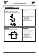
M1 B3+B5 M1 B3+B5 M2 V6+V3 M6 B7+B5III M2 V6+V3 M6 B7+B5III SK 02 SK 12 SK 22 SK 32 SK 42 SK 52 SK 62N SK 11E SK 21E SK 31E SK 41E SK 51E M5 B6+B5II M4 V5+V1 M5 B6+B5II M4 V5+V1 M3 B8+B5I M3 B8+B5I M1 B3+B5 M1 B3+B5 * M6 B7+B5III M6 B7+B5III M2 V6+V3 SK 62 SK 72 SK 82 SK 92 SK 102 SK 63* SK 73* SK 83* SK 93* SK 103* SK 03 SK 13 SK 23 SK 33N SK 43 SK 53 M5 B6+B5II M4 V5+V1 * M5 B6+B5II M4 V5+V1 M3 B8+B5I M3 B8+B5I -44- M2 V6+V3 B2000-0413 www.nord.
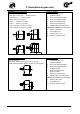
M1 B3+B5 * M1 M2 V3+V6 M6 B7+B5III M6 M2 SK 372.1 SK 572.1 SK 672.1 SK 373.1 SK 573.1 SK 673.1 SK 472 SK 572 SK 672 SK 772 SK 872 SK 972 SK 473 SK 573 SK 673 SK 773 SK 873* SK 973* M4 M5 B6+B5II M4 V1+V5 M5 M3 M3 B8+B5I M1 M1 * M6 M2 M2 * SK 372.1F SK 572.1F SK 672.1F SK 373.1F SK 573.1F SK 673.1F SK 772.1 SK 872.1 SK 972.1 SK 773.1* SK 873.1* SK 973.1* M6 * M4 M5 * M5 M4 M3 M3 www.nord.
M1 * M2 * SK 772.1F SK 872.1F SK 972.1F SK 773.1F* SK 873.1F* SK 973.1F* M6 * M5 M4 * M3 M1 M1 M2 M6 M6 M2 SK 072.1 F SK 172.1 F SK 072.1 SK 172.1 M4 M4 M5 M3 M5 M4 M3 38 -46- B2000-0413 www.nord.
M1 B3+B5 M2 V6+V3 SK 0 SK 01 SK 20 SK 25 SK 30 SK 33 M6 B7+B5III M4 V1+V5 M5 B6+B5II M3 B8+B5I M1 B3+B5 M2 V6+V3 SK 000 SK 010 SK 200 SK 250 SK 300 SK 330 M6 B7+B5III M5 B6+B5II M4 V1+V5 M3 B8+B5I II3G / II3D 35, 37 www.nord.
M1 H1 M1 H1 M2 H6 M6 H3 M2 H6 M6 H3 SK 2382 SK 3382 SK 4382 SK 5382 SK 1282 SK 2282 SK 3282 SK 4282 SK 5282 M4 H5 M5 H4 M5 H4 M4 H5 M3 H2 M3 H2 M1 H1 M1 H1 M2 H6 M6 H3 M2 H6 M6 H3 ** SK 6282* SK 7282* SK 8282* SK 9282* SK 10282* SK 11282* SK 6382 SK 7382 SK 8382 SK 9382 SK 10382 SK 11382 SK 12382 ** ** * * M4 H5 M5 H4 M4 H5 SK 0182NB SK 0282NB SK 1382NB * M3 H2 M5 H4 M3 H2 37 -48- B2000-0413 www.nord.
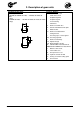
M1 B3 M1 B3 M6 V6 M2 B6 SK 92172 SK 92372 SK 92672 SK 92772 M2 B6 M6 V6 SK 92072 M4 B3I M4 B3I M5 V5 M5 V5 M3 B8 M3 B8 M1 B3 M1 B3 M6 V6 M2 B6 M2 B6 M6 V6 SK 9012.1 SK 9016.1 SK 9022.1 SK 9032.1 SK 9042.1 SK 9052.1 SK 9062.1 SK 9072.1 SK 9082.1 SK 9086.1 SK 9092.1 SK 9096.1 M4 B3I SK 9013.1 SK 9017.1 SK 9023.1 SK 9033.1 SK 9043.1 SK 9053.1 M4 B3I M5 V5 M3 B8 M3 B8 www.nord.
M1 H1+B5I M6 H6+V3 M1 H1+B5I M2 H4+B5 M2 H4+B5 M6 H6+V3 SK 92172 SK 92372 SK 92672 SK 92772 SK 92072 M5 H5+V1 M4 H3+B5II M5 H5+V1 M4 H3+B5II M3 H2+B5III M3 H2+B5III M1 M1 M6 M6 SK 92072.1 SK 92172.1 SK 92372.1 SK 92672.1 SK 92772.1 M4 SK 93072.1 SK 93172.1 SK 93372.1 SK 93672.1 SK 93772.1 M2 M5 M5 M4 M3 M3 -50- M2 B2000-0413 www.nord.
M1 H1+B5I M1 H1+B5I M6 H6+V3 M2 H4+B5 M2 H4+B5 M6 H6+V3 SK 9012.1 SK 9016.1 SK 9022.1 SK 9032.1 SK 9042.1 SK 9052.1 SK 9062.1 SK 9072.1 SK 9082.1 SK 9086.1 SK 9092.1 SK 9096.1 SK 9013.1 SK 9017.1 SK 9023.1 SK 9033.1 SK 9043.1 SK 9053.1 M4 H3+B5II M4 H3+B5II M5 H5+V1 M3 H2+B5III M5 H5+V1 M3 H2+B5III M1 B3 M1 B3 M2 B6 M2 B6 M6 V6 M6 V6 SK 02050 SK 12063 SK 12080 SK 32100 SK 42125 M4 B3I SK 13050 SK 13063 SK 13080 SK 33100 SK 43125 M4 B3I M5 V5 M5 V5 M3 B8 www.nord.
M1 H1+B5I M1 H1+B5I M2 H4+B5 M6 H6+V3 M2 H4+B5 M6 H6+V3 SK 02050 SK 12063 SK 12080 SK 32100 SK 42125 SK 13050 SK 13063 SK 13080 SK 33100 SK 43125 M5 H5+V1 M4 H3+B5II M4 H3+B5II M3 H2+B5III M5 H5+V1 M3 H2+B5III M1 B3 M1 H1+B5I M2 B6 M6 V6 M6 H6+V3 SK 02040 SK 02040 M2 H4+B5 M4 H3+B5II M4 B3I M5 V5 M3 H2+B5III M3 B8 -52- M5 H5+V1 B2000-0413 www.nord.
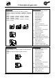
M1 B3 M6 V5II M2 B6 SK 1S32SK 1S63 SK 2S32NB – SK 2S63NB SK 1SU32 – SK 1SU63 SK 2SU32NBSK 2SU63NB SK 1SM31 – SK 1SM63 SK 2SM40 – SK 2SM63 M4 B6II M5 V5 M3 B8 M1 H1+B5I M2 H4+B5 M6 H6+V1I SK 1S32SK 1S63 SK 2S32NB – SK 2S63NB SK 1SU32 – SK 1SU63 SK 2SU32NBSK 2SU63NB SK 1SM31 – SK 1SM63 SK 2SM40 – SK 2SM63 M4 H3+B5II M5 H5+V1 M3 H2+B5III 39 www.nord.
6. Appendix 6.2 Lubricants When changing oil or filling for the first time, the type of lubricant stated on the rating plate must be used. The following table shows the proprietary brands or product names according to the gear oil types stated on the rating plate (see Section 3.4). This means that a product corresponding to the type of oil shown on the rating plate must be used. In special cases, the designation of the specified product is stated on the type plate of the gear unit.
6. Appendix 6.3 Torque values Bolt Torques [Nm] Size Screw connections in the strength classes Sealing Threaded pin screws on coupling 8.8 10.9 12.9 M4 3.2 5 6 - - M5 6.
6. Appendix 6.5 Declaration of Conformity -56- B2000-GB-0413 www.nord.
6. Appendix www.nord.
DRIVESYSTEMS www.nord.
NORD DRIVESYSTEMS GROUP www.nord.com/locator Getriebebau NORD GmbH & Co. KG Rudolf-Diesel-Straße 1 22941 Bargteheide, Germany Fon +49 (0) 4532 / 289 - 0 Fax +49 (0) 4532 / 289 - 2253 info@nord.com, www.nord.com Member of the NORD DRIVESYSTEMS GROUP DRIVESYSTEMS Mat.-Nr.