
User guide


- 5 -
Operating and assembly instructions spring-loaded brake FDW – ATEX
Inspection / maintenance
Safety measures and actions
De-energise motor and brake and protect them from an
accidental reclosure.
The brake must not be opened for inspection in an explosive atmosphere.
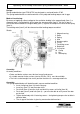
Inspection:
Turn out the radially arranged screw plug (item 12),
measure the existing air gap (feeler gauge 5 mm wide) and compare
it with table 2 - below.
Screw down the screw plug (item 12) again – pay attention to O-ring -
and secure it with locking paint.
To be noted!
When the max. air gap is reached, the brake rotor has to be exchanged!
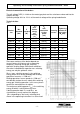
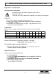
Table 2
FDW 08 10 13 15 17 20 23 26 30
a
Nom
+0,1
0,2 0,2 0,3 0,3 0,3 0,4 0,4 0,5 0,5
a
max
0,5 0,6 0,8 0,8 0,8 0,9 0,9 1,0 1,0
Rotor size (new) 7,5 8,5 10,3
12,5
14,5
16 18 20 20
Dimensions indicated in mm
Control PTC thermistor: Resistance (at 20°C) < 100 Ohm
To be noted: Cable diameter 3,7 mm
The working air gap cannot be readjusted.
When assembling the controlled brake, the Cu-washers under the
fastening screws have to be replaced.
Inspection intervals:
When using the spring-loaded brakes:
as a working brake
at least every 3000 operating hours, refer to additional information
as a holding brake
depending on operating conditions and load every 2 to 3 years
with emergency-stop properties
refer to additional information