
User guide


- 4 -
Operating and assembly instructions spring-loaded brake FDW – ATEX
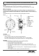
Electrical connection of the brakes
The coil voltage (VDC) is visible on the motor type plate and has also been embossed into the
magnet housing.
Operating voltage 90 % to 110 % of the nominal voltage of the spring-loaded brake.
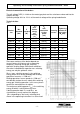
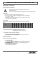
Technical data:
Table 1
Since wear and tear of the brake depends on
several factors of influence such as operating
frequency, switching energy per switching
operation, braking torque and climatic conditions
the values indicated with regard to max. switching
energy can only be guidance values.
W
Rmax
(max. switching energy) is the switching
energy which must not be exceeded with braking
operations from max. > 1500 min
-1
.
Braking operations from a speed of > 1500 min
-1
considerably reduce the max. admissible switching
energy per switching operation. In this case, please
contact the manufacturers for advice.
The maximum switching power P
max
is the switching
energy W which is achievable every hour.
If during operation both P
max
and W
max
are
simultaneously nearly reached, the diagram
(W
max
depending on the hourly switching time)
shown in the operating instructions has to be used.
Brakes
size
M
bN
Standard
(Nm)
P
Standard
(W)
W
Rmax
max.
friction
energy
per
braking
(J)
P
R
max.
admissible
friction
power
(J/h)
Fastening
screws
Tightening
moment of
the screws
M
A
(Nm)
FDW 08 5 33 1,5x10
3
140x10
3
3 x M4 3
FDW 10 10 42 3,0x10
3
180x10
3
3 x M5 6
FDW 13 20 50 6x10
3
230x10
3
3 x M6 10
FDW 15 40 63 12x10
3
280x10
3
3 x M6 10
FDW 17 60 75 17x10
3
360x10
3
3 x M8 25
FDW 20 100 96
25x10³ 450x10³
3 x M8 25
FDW 23 150 114
37x10³ 540x10³
3 x M8 25
FDW 26 250 150
52x10³ 630x10³
3 x M10 50
FDW 30 400 210
75x10³ 720x10³
6 x M10 50