GB B 1091-1 Motors in fi operation for Category 3D Planning guideline for B 1091
Motors in fi operation for Category 3D – Planning guideline for B 1091 Pos: 2 /Anleitungen/Motoren/B1091-1 Projektierungsleitfaden zur B1091/0. Prolog/0.2 Bestimmungsgemäße Verwendung der Drehstrom-Asynchronmotoren im Frequenzumrichterbetrieb[B1091-1] @ 2\mod_1358777562957_388.
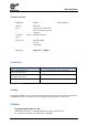
Documentation Pos: 4 /Anleitungen/Motoren/B1091-1 Projektierungsleitfaden zur B1091/0. Prolog/0.3 Dokumentation - Versionsliste [B1091-1] @ 2\mod_1358777563534_388.docx @ 54072 @ @ 1 Documentation Planning Guideline Designation: B1091-1 Part No.
Motors in fi operation for Category 3D – Planning guideline for B 1091 4 B 1091-1 GB-3213
Table of Contents Pos: 8 /Anleitungen/Steuermodule/Inhaltsverzeichnis @ 0\mod_1317978518480_388.docx @ 4078 @ @ 1 Table of Contents === Ende der Liste für Textmarke Inhaltsverzeichnis === 1. Technical explanations ............................................................................................................................... 8 1.1 General .............................................................................................................................................. 8 1.
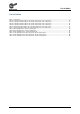
Motors in fi operation for Category 3D – Planning guideline for B 1091 Pos: 10 /Anleitungen/Steuermodule/Abbildungsverzeichnis @ 0\mod_1317978515699_388.docx @ 3917 @ @ 1 List of illustrations === Ende der Liste für Textmarke Abbildungsverzeichnis === Figure 1: Selection of V/f characteristic curves ...................................................................................................... 10 Figure 2: Motor 100L/4, 50 Hz characteristic curve ....................................................
List of tables Pos: 12 /Anleitungen/Steuermodule/Tabellenverzeichnis @ 0\mod_1317978519199_388.docx @ 4124 @ @ 1 List of tables === Ende der Liste für Textmarke Tabellenverzeichnis === Table 1: Version list ................................................................................................................................................. 3 Tabelle 2: Parameterisation data for the 50 Hz characteristic curve, IE1 motors ..................................................
Motors in fi operation for Category 3D – Planning guideline for B 1091 1. Technical explanations Pos: 15 /Anleitungen/Motoren/B1091-1 Projektierungsleitfaden zur B1091/1. Technische Erläuterungen/1.1 Allgemeines [B1091-1] @ 2\mod_1358235620867_388.docx @ 53281 @ 2 @ 1 1.1 General The Category 3D motors supplied by NORD DRIVESYSTEMS comply with standard EN 50281-1-1 (electrical equipment for use in areas with inflammable dust) and EN 50014 (Electrical equipment for explosion hazard areas).
1 Technical explanations Pos: 18 /Anleitungen/Motoren/B1091-1 Projektierungsleitfaden zur B1091/1. Technische Erläuterungen/1.3 Verdrahtung [B1091-1] @ 2\mod_1358237941880_388.docx @ 53328 @ 2 @ 1 1.3 • • • • Wiring: No filters which come into the resonance range may be wired between the inverter and the motor The resulting overvoltage could damage the insulation of the cable or the motor. Only filters which are prescribed or approved by the supplier of the frequency inverter may be used.
Motors in fi operation for Category 3D – Planning guideline for B 1091 Pos: 21 /Anleitungen/Motoren/B1091-1 Projektierungsleitfaden zur B1091/1. Technische Erläuterungen/1.5 Frequenzumrichterzuordnung und Auswahl der Betriebsart [B1091-1] @ 2\mod_1358240883977_388.docx @ 53380 @ 2 @ 1 1.
1 Technical explanations Pos: 23 /Anleitungen/Motoren/B1091-1 Projektierungsleitfaden zur B1091/1. Technische Erläuterungen/1.6 Beispiele [B1091-1] @ 2\mod_1358250027977_388.docx @ 53430 @ 2 @ 1 1.6 Examples Pos: 24 /Anleitungen/Motoren/B1091-1 Projektierungsleitfaden zur B1091/1. Technische Erläuterungen/1.6.1 Beispiel 1 Motor 100L/4 [B1091-1] @ 2\mod_1358246005266_388.docx @ 53405 @ 35555 @ 1 1.6.1 1.
Motors in fi operation for Category 3D – Planning guideline for B 1091 100 Hz characteristic curve Motor in delta circuit (230 V / 50 Hz), frequency inverter 3.
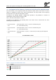
1 Technical explanations 87 Hz characteristic curve Motor in delta circuit (230 V / 50 Hz), frequency inverter 4.0 kW Figure 4: Motor 100L/4, 87 Hz characteristic curve Legend Motor output power in [kW] Torque in [%] Pos: 25 /---------- Seitenumbruch ---------- @ 1\mod_1329145698658_0.
Motors in fi operation for Category 3D – Planning guideline for B 1091 Pos: 26 /Anleitungen/Motoren/B1091-1 Projektierungsleitfaden zur B1091/1. Technische Erläuterungen/1.6.2 Beispiel 2 Motor 100L/4 [B1091-1] @ 2\mod_1358250210775_388.docx @ 53455 @ 35 @ 1 1.6.2 2. Example: motor 100L/4 Motor type plate information: Nominal voltage 400/690 V Nominal frequency: 50 Hz Nominal power: 2.
1 Technical explanations Pos: 28 /Anleitungen/Motoren/B1091-1 Projektierungsleitfaden zur B1091/1. Technische Erläuterungen/1.7 Motordaten für die Umrichterparametrierung [B1091-1] @ 2\mod_1358252268103_388.docx @ 53480 @ 2 @ 1 1.7 Motor data for parameterisation of the frequency inverter Motor types: IE1 and IE2 motors Category: 3D Pos: 29 /Anleitungen/Motoren/B1091-1 Projektierungsleitfaden zur B1091/1. Technische Erläuterungen/1.7.
Motors in fi operation for Category 3D – Planning guideline for B 1091 1.7.2 Parameterisation data for the 87 Hz characteristic curve, IE1 and IE2 motors Motor type IE1 fN nN IN UN PN [Hz] [rpm] [A] [V] [kW] 63S/4 3D 50 1335 0.95 230 0.12 RSt cos φ Circuit 0.64 ∆ 68.00 [Ω] 63L/4 3D 50 1360 1.18 230 0.18 0.64 ∆ 47.37 71S/4 3D 50 1365 1.3 230 0.25 0.79 ∆ 39.9 71L/4 3D 50 1380 1.89 230 0.37 0.71 ∆ 22.85 80S/4 3D 50 1385 2.62 230 0.55 0.75 ∆ 15.
1 Technical explanations Pos: 33 /Anleitungen/Motoren/B1091-1 Projektierungsleitfaden zur B1091/1. Technische Erläuterungen/1.7.3 Parametrierdaten 100 Hz- Kennlinie, IE1- und IE2- Motoren [B1091-1] @ 2\mod_1358264293717_388.docx @ 53581 @ 3 @ 1 1.7.3 Parameterisation data for the 100 Hz characteristic curve, IE1 and IE2 motors Motor type IE1 fN nN IN UN PN [Hz] [rpm] [A] [V] [kW] cos φ Circuit RSt [Ω] 63S/4 3D 100 2850 0.84 400 0.18 0.59 ∆ 68.00 63L/4 3D 100 2880 0.95 400 0.
Motors in fi operation for Category 3D – Planning guideline for B 1091 2. Technical Data Data: Motor type: IE1 and IE2 * Category: 3D Mains voltage: 400 V Circuit: See tables Surface temperature: T125 °C / T140 °C Ambient temperature Tu: max. 40 °C * Values also apply for IE2 (Labelling xH), e.g. 80LH/4 Pos: 35 /Anleitungen/Motoren/B1091-1 Projektierungsleitfaden zur B1091/2. Technische Daten/2.1 Motoren/2.1 Motoren [B1091-1] @ 2\mod_1358759456932_388.docx @ 53819 @ 2 @ 1 2.
2 Technical Data Pos: 37 /Anleitungen/Motoren/B1091-1 Projektierungsleitfaden zur B1091/2. Technische Daten/2.1 Motoren/2.1.1 Motoren, 50 Hz Nennpunkt [B1091-1] @ 2\mod_1358417752109_388.docx @ 53691 @ 3 @ 1 2.1.1 Motors, 50 Hz nominal point Motor type Circuit see 1.
Motors in fi operation for Category 3D – Planning guideline for B 1091 Pos: 39 /Anleitungen/Motoren/B1091-1 Projektierungsleitfaden zur B1091/2. Technische Daten/2.1 Motoren/2.1.2 Motoren, 87 Hz Nennpunkt [B1091-1] @ 2\mod_1358765717448_388.docx @ 53868 @ 3 @ 1 2.1.
2 Technical Data 2.1.3 Motors, 100 Hz nominal point Motor type Delta circuit Frequency inverter power and rated current Motor power in [kW] at 50 Hz (upper) and 100 Hz (lower) 3 10 20 30 40 50 60 70 0,55 kW 0.09 1,6 A 63S/4 0.18 0,55 KW 0.12 1,6 A 63L/4 0.23 0.5 52 6 0.7 54 30 0.6 64 134 0.8 59 185 0.6 73 401 0.8 65 422 0,55 kW 0.18 1,6 A 0.35 1.0 58 30 1.1 64 181 1.3 72 462 0,55 kW 0.27 1,6 A 0.42 0,75 kW 0.39 2,2 A 80S/4 0.67 1.4 54 0 1.8 48 0 1.6 62 152 2.3 61 163 1.8 69 475 2.5 64 410 3.
Motors in fi operation for Category 3D – Planning guideline for B 1091 2.2 Motors with external fan Information Interpolation A linear interpolation of the data between adjacent frequencies is permissible. Pos: 44 /---------- Seitenumbruch ---------- @ 1\mod_1329145698658_0.
2 Technical Data Pos: 45 /Anleitungen/Motoren/B1091-1 Projektierungsleitfaden zur B1091/2. Technische Daten/2.2 Motoren mit Fremdlüfter/2.2.1 Motoren mit Fremdlüfter, 50 Hz Nennpunkt [B1091-1] @ 2\mod_1358771466655_388.docx @ 53918 @ 3 @ 1 2.2.1 Motors with external fan, 50 Hz nominal point See below Motor type For the circuit diagram see 1.7 for legend Frequency inverter power and rated current Motor power in [kW] at 50 Hz (upper) and 100 Hz (lower) 3 10 20 30 40 50 60 70 80 90 100 fs [Hz] 0,55 kW 0.
Motors in fi operation for Category 3D – Planning guideline for B 1091 Pos: 46 /Anleitungen/Motoren/B1091-1 Projektierungsleitfaden zur B1091/2. Technische Daten/2.2 Motoren mit Fremdlüfter/2.2.2 Motoren mit Fremdlüfter, 87 Hz Nennpunkt [B1091-1] @ 2\mod_1358773222601_388.docx @ 53968 @ 3 @ 1 2.2.
2 Technical Data 2.2.3 Motors with external fan, 100 Hz nominal point Motor type Delta circuit Frequency inverter power and rated current Motor power in [kW] at 50 Hz (upper) and 100 Hz (lower) 3 10 20 30 40 50 60 70 0,55 kW 0.09 1,6 A 0.18 0,55 KW 0.13 1,6 A 0.25 0,55 kW 0.18 1,6 A 0.34 0.6 71 6 0.9 68 30 1.2 71 30 0.6 71 134 0.9 68 185 1.2 71 181 0.6 71 401 0.9 68 422 1.2 71 462 0,55 kW 0.24 1,6 A 0.42 0,75 kW 0.38 2,2 A 0.67 1,1 kW 0.52 3,0 A 0.99 1.6 63 0 2.5 66 0 3.5 67 0 1.6 63 152 2.
Motors in fi operation for Category 3D – Planning guideline for B 1091 3. Appendix Pos: 49 /Anleitungen/Motoren/B1091-1 Projektierungsleitfaden zur B1091/3. Anhang [B1091-1]/3.1 Abkürzungen [B1091-1] @ 2\mod_1358779308835_388.docx @ 54121 @ 2 @ 1 3.
Pos: 52 /Anleitungen/Steuermodule/Stichwortverzeichnis @ 0\mod_1317978518730_388.
6052102 / 3213