
Manual
6. Appendix
www.nord.com B1050-GB-0213 -29-
6. Appendix
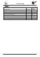
6.1 Versions and maintenance
Note!
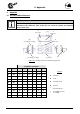
The version and the position of the oil drain, vent and oil level should be primarily
obtained from the dimension sheet. If this does not contain any details, the following
details can be used.
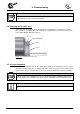
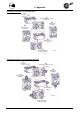
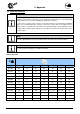
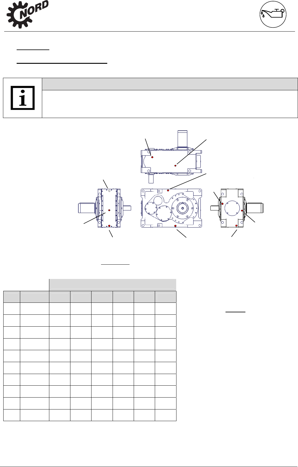
Figure 6-1: Position of the oil screws in the gear unit
Installation orientation
No. Thread M1 M2 M3 M4 M5 M6
1 G1 A
S
1)
E S
1)
A / E A / E
2 G1
E S
1)
A S
1)
A / E A / E
3 G1 E
S E S
1)
S S
1)
4 G1
E --- E S S
1)
S
5 G1
--- --- --- --- --- ---
6 G1
A / E
2)
A / E
2)
A S
1)
S
1)
7 G1
S
1)
E S
1)
A S
1)
S
1)
8 G1 S
A S
1)
E A E
9 G1
S
1)
A S E E A
10 G1
A E E A S
1)
S
1)
Legend
A
Oil drain
E
Vent
S
Oil level screw
G
Closed
1)
Special oil level
2)
According to cover
assembly
3
(both sides)
4
(both sides)
(6)
(according to assembly)
7
6
(according to assembly)
2
(both sides)
9
8
10
1
(both sides)