Intelligent Drivesystems, Worldwide Services GB B1050 Operating and Maintenance Instructions for Industrial Gear Units SK 7207 - SK 15507 DRIVESYSTEMS
Contents 1. 1.1 1.2 1.3 1.4 1.5 1.6 Notes .............................................................................................................................. 4 General information ........................................................................................................ 4 Safety and information symbols ..................................................................................... 4 Correct use ..................................................................................
1. Notes 1. Notes 1.1 General information Read the Operating Manual carefully prior to performing any work on or putting the gear unit into operation. Strict compliance with the instructions in this Operating Manual is essential. Getriebebau NORD accepts no liability for damage to persons, materials or assets as a result of the non-observance of this Operating Manual, operating errors or incorrect use. General wearing parts, e.g. radial seals are excluded from the warranty.
1. Notes 1.4 Safety information All work including transportation, storage, installation, electrical connection, commissioning, servicing, maintenance and repair must be performed only by qualified specialist personnel. It is recommended that repairs to NORD Products are carried out by the NORD Service department. Danger! Installation and maintenance work must only be performed when gear units are at a standstill and have cooled down. The drive must be isolated and secured to prevent accidental start-up.
2. Description of Gear Unit 2. Description of gear units 2.
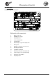
2. Description of Gear Unit 2.2 Name plate Example of a gear unit name plate.
3. Storage, Transport, Preparation, Installation 3. Storage, transport, preparation, installation Please observe all of the general safety information in Section 1.4, 1.3 and in the individual sections. 3.1 Storing the gear unit For short-term storage before commissioning, please observe the following: Store in the fitting position (see Section 6.
3.Storage, Transport, Preparation, Installation 3.3 Transporting the gear unit Danger! To prevent injury, the danger area must be generously cordoned off. Standing under the gear unit during transport is extremely dangerous. Attention! Avoid damage to the gear unit. Impacts to the free ends of the shafts may cause internal damage to the gear unit. Use adequately dimensioned and suitable means of transportation. Lifting tackle must be designed for the weight of the gear unit.
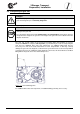
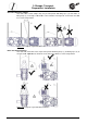
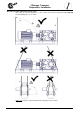
3. Storage, Transport, Preparation, Installation Gear units with motor adapter Gear units with a motor adapter may only be transported with lifting ropes (2) and chains or lifting straps (1) at an angle of 90° to 70° to the horizontal. The ring bolts on the motor must not be used for transportation. Figure 3-2: Transport of gear unit with motor Drive units with V-belt drive Gear units with V-belt drive must only be transported with lifting straps (1) and lifting ropes (2) at an angle of 90° (vertical).
3.Storage, Transport, Preparation, Installation Gear units on motor swing base or base frame Gear units on a motor swing base or base frame must only be transported with vertically tensioned lifting ropes (1) or chains. Figure 3-4: Transport of gear unit with motor swing base or base frame www.nord.
3. Storage, Transport, Preparation, Installation 3.4 Preparing for installation The drive unit must be inspected and may only be installed if no damage is apparent. In particular the radial seals and the sealing caps must be inspected for damage. All bare metal surfaces and shafts of the gear unit are protected against corrosion with oil, grease or corrosion protection agents before shipping.
3.Storage, Transport, Preparation, Installation Welding of the gear unit is prohibited. The gear unit must not be used as the earth connection for welding work, as this may cause damage to the bearings and gear wheels. The gear unit must be installed in the correct orientation (see Section 6.1). All gear unit feet on each side or all flange screws must be used. Bolts must have a minimum quality of 8.8. The bolts must be tightened to the correct torques (refer to Section 6.4 for torque values).
3. Storage, Transport, Preparation, Installation 3.7 Fitting push-on gear units Achtung! The bearings, gear wheels, shafts and housing may be damaged by incorrect fitting. The push-on gear unit must be fitted onto the shaft using a suitable puller, which will not exert damaging axial forces on the gear unit. In particular, do not hit the gear unit with a hammer. Assembly and subsequent dismantling is aided by applying an anti-corrosive lubricant to the shaft before fitting.
3.Storage, Transport, Preparation, Installation Figure 3-8: Securing Figure 3-9: Dismantling 1 Fastening element 2 Securing ring 3 Assembly – threaded rod 4 Assembly – threaded nut 6 Protective cover 7 Disassembly of threaded rod 8 Disassembly element 9 Disassembly – threaded nut When assembling push-on gears with torque supports, the support must not be distorted. Distortion-free assembly is made easier if an elastic element (Option DG) is used. www.nord.
3. Storage, Transport, Preparation, Installation 3.8 Torque support The length of the torque support can be adjusted within a certain range. The torque support consists of a fork head with a bolt (1), a threaded bolt (2), a maintenance-free joint head (3) and a fork plate with a bolt (4). Assembly should be carried out from the side of the machine, in order to reduce the bending moment on the machine shaft. Tension and pressure and installation upwards or downwards are not permissible.
3.Storage, Transport, Preparation, Installation 3.10 Fitting the covers Danger! Shrink discs and exposed rotating shaft ends require contact guards in order to prevent injuries. A cover (Option H) can be used as a guard. If this does not achieve sufficient protection against contact according to the required protection type, the machinery and plant constructor must ensure this be means of special attached components. All fixing screws must be used and tightened to the correct torque. (See Chapter 6.
3. Storage, Transport, Preparation, Installation Assembly procedure to attach a standard motor to the IEC adapter (Option IEC)/NEMA adapter 1. Clean motor shaft and flange surfaces of motor and adapter and check for damage. Mounting dimensions and tolerances of the motor must conform to DIN EN 50347/NEMA MG1 Part 4. 2. Push the coupling sleeve onto the motor shaft so that the motor parallel key engages into the groove in the sleeve on tightening. 3.
3.Storage, Transport, Preparation, Installation 3.12 Fitting the cooling coil to the cooling system For the inlet and outlet of cooling fluid, connections with G ½ pipe thread are located in the casing cover for the fitting of pipes or hoses. Remove the drain plug from the screw connectors prior to assembly to avoid any contamination of the cooling system. The screw connectors should be connected with the coolant circuit, which must be provided by the operator.
3. Storage, Transport, Preparation, Installation Attention! With circulation lubrication (LC) use the connection diagram included by NORD. (1) Gear unit intake connection (2) Pump / cooling system intake connection (3) Cooling system pressure connection (4) Gear unit pressure connection (5) Temperature monitoring (optional) Figure 3-13: Industrial gear unit with CS1 and CS2 cooling systems Figure 3-14: Hydraulic diagram of the industrial gear unit with CS1 and CS2 cooling systems 3.
4. Commissioning 4. Commissioning 4.1 Checking the oil level The oil level must be checked prior to commissioning. See Section 5.2. 4.2 Lubricant cooling with internal water cooler Caution! The drive may only be commissioned after the cooling coil has been connected to the cooling circuit, and the cooling circuit has been put into operation. The coolant must have a similar thermal capacity as water (specific thermal capacity at 20°C c=4.18 kJ/kgK).
4. Commissioning Caution! The cooling system filter must be checked regularly and replaced if the contamination indicator triggers. Note! With a thermostat in the cooling water inlet, the volume of cooling water can be adjusted to the actual requirements. 4.4 Lubricant cooling with external oil/water cooler (cooling system) Attention! The operating instructions for the cooling system must be observed.
4. Commissioning Caution! The contact guard must be inspected for damage (e.g. due to incorrect transportation) as contact with the fan may overload the gear unit. 4.6 Checking the Taconite seals If Taconite seals are installed, check whether there is a gap between the bearing cover plates (Pos. 1 and Pos. 2), and that this is filled with grease. Relubrication is carried out via the conical grease nipple M10x1 - DIN 71412 (Pos.3). Pos.1 Grease-filled gap Pos.3 Pos.
4. Commissioning 4.8 Checklist Checklist Object of the check Checked on: Information – see Section Is the vent screw screwed in? Sec. 3.3 Does the required configuration conform with the actual installation? Sec. 6.1 Are the external gear shaft forces within permitted limits (chain tension)? Sec. 3.5 Is the torque support correctly fitted? Sec. 3.6 Are contact guards fitted to rotating components? Sec. 3.8 Is the cooling system connected? Sec. 3.14/4.
5. Service and Maintenance 5. Service and maintenance 5.
6. Appendix Check the oil level Section 6.1 describes the versions and the corresponding oil level screws. With double gear units, the oil level must be checked on both units. The pressure vent must be at the position marked in Section 6.1. Gear unit types that are not supplied full of oil must be filled before the oil level is checked. (See “Changing the oil”) Checking the oil level: 1. The oil level may only be checked when the gear unit is at a standstill and has cooled down.
5. Service and Maintenance Re-lubricating the Taconite seals The grease nipples of the Taconite seals must be filled with grease until clean grease emerges from the grease gap. Remove and dispose of escaping grease. Recommended grease: Petamo GHY 133N (see Section 6.2: Klüber Lubrication). Note! Optimal re-lubrication is achieved by rotating the gear unit shaft in 45° steps when lubricating and pressing in grease until clean grease emerges from the shaft.
6. Appendix 7. Wait at least 15 minutes, or at least 30 minutes if an oil level tank is used, and then check the oil level. Proceed as described in Section 5.2. Replacing the oil filter The oil filter must be changed according to the operating instructions from the supplier. Cleaning or replacing the vent plug or the vent filter In case of heavy soiling, unscrew the vent plug or vent filter and clean it thoroughly or fit a new vent plug or vent filter with a new sealing ring.
6. Appendix 6. Appendix 6.1 Versions and maintenance Note! The version and the position of the oil drain, vent and oil level should be primarily obtained from the dimension sheet. If this does not contain any details, the following details can be used. 4 3 (both sides) (both sides) (6) 2 (according to assembly) (both sides) 9 8 7 6 1 (according to assembly) (both sides) 10 Figure 6-1: Position of the oil screws in the gear unit Installation orientation No.
6.
6. Appendix 6.2 Lubricant quantities Note! After changing the lubricant, and in particular after the initial filling, the oil level may change during the first few hours of operation, as the oil galleries and hollow spaces only fill gradually during operation. The oil level is still within the permissible tolerance.
6.
6. Appendix 6.
6. Appendix Lubricant table This table shows comparable lubricants from various manufacturers. The manufacturer can be changed within a particular viscosity or lubricant type. Getriebebau NORD must be contacted in case of change of viscosity or lubricant type, as otherwise no warranty for the functionality of our gearboxes can be accepted.
6. Appendix 6.4 Bolt torque values Bolt Torques [Nm] Size Screw connections in the strength classes 8.8 10.9 Cap screws 12.
6. Appendix 6.
NORD Drivesystems | Global vor Ort www.nord.com/locator Getriebebau NORD GmbH & Co. KG Rudolf-Diesel-Straße 1 22941 Bargteheide, Germany Fon +49 (0) 4532 / 289 - 0 Fax +49 (0) 4532 / 289 - 2253 info@nord.com, www.nord.com Member of the NORD DRIVESYSTEMS GROUP DRIVESYSTEMS Mat.-Nr.