APC-OP Manual Addendum – Section 10 LCD Front Panel Interface 8-2010 Nor-Cal Products, Inc. 1967 So. Oregon Yreka, CA 96097 USA Tel: 800-824-4166 or 530-842-4457 Fax: 530-842-9130 www.n-c.
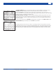
10.0 Front Panel Interface Operation Controller models with a part number in the form APC-x50-A have a touch screen LCD front panel interface, in addition to a Serial and Analog/TTL port. On these models, the functionality of the Serial and Analog/TTL interfaces is identical to that previously described in sections 6.0 and 7.0 of the APC-OP Manual. This section is dedicated to describing the use and operation of the front panel touch screen.
10.1 Commonly Used Function Buttons Navigating through the various menus of the front panel LCD interface, the user will find that some functions and associated buttons are used in more than one place. This includes the SAVE, SET VALUE, BACK SPACE, CLEAR, BACK and EXIT functions. The SAVE function is generally found on set-up type screens. This button must be pressed before exiting to another page allowing the set-up information to be stored in NVRAM.
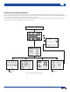
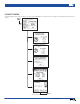
10.3 CONFIGURE SETPOINTS CONFIGURE SETPOINTS is the first sub-menu directly accessible from the MAIN MENU screen. Figure 10.2 shows a navigation tree detailing this part of the function software. MAIN MENU Figure 10.2 – CONFIGURE SETPOINTS Navigation Tree More similar ones for SET GAIN, SET PHASE and SET The SELECT SETPOINT page allows the user to choose which set-point is to have its parameters manipulated. All parameters of setpoints 1 to 5 can be set from this screen.
The SELECT ATTRIBUTE page for each setpoint allows the user to pick which attribute(s) to program. Pressing SETPOINT will bring up a number pad screen via which a numerical value can be given to the setpoint. Pressing the SP TYPE button repeatedly causes the setpoint type to toggle between “valve” and “pressure” – in other words choosing a “valve” type here means that the setpoint, when activated, will drive the valve to a prescribed position as opposed to controlling to a particular pressure.
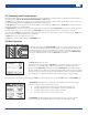
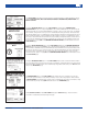
10.4 UTILITY MENU The UTILITY MENU is another sub-menu directly accessible from the MAIN MENU screen. Figure 10.3 shows a navigation tree detailing this part of the function software. MAIN MENU more... Figure 10.3 – UTILITY MENU Navigation Tree 6 Visit our Web Site www.n-c.
The UTILITY MENU page simply serves as the means to reach the five functions contained under this category, including INITIALIZE VALVE, RESET CONTROLLER, DIAGNOSTIC INFORMATION, REMOTE MODE and DISPLAY UTILITIES. Pressing the INITIALIZE VALVE button on the UTILITY MENU page brings up the CONFIRM VALVE INITIALIZATION dialogue screen. By pressing YES here, the controller will initialize the valve, which means all other functions will cease to respond until initialization is complete.
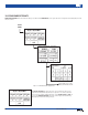
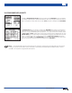
10.5 CONFIGURE DISPLAY UNITS The ability to CONFIGURE DISPLAY UNITS is directly accessible form the MAIN MENU. This screen allows the user to change engineering units for both pressure and valve position. Also, this page is used to set the full scale range of each gauge used. Please make sure to press the SAVE button prior to exiting back to the MAIN MENU. The CONTROL MENU page, also directly accessible from the MAIN MENU, is the primary screen intended for manual operation.
Appendix II - Limited Warranty and Intellectual Property Coverage Products manufactured by Nor-Cal Products, Inc. (hereinafter referred to as “Nor-Cal”) are warranted against defects in material and workmanship for a period of twelve (12) months from the date of shipment from Nor-Cal to the buyer. Any modification to the product by the buyer or their agent voids this warranty. Liability under this warranty is expressly, limited to replacement or repair (at Nor-Cal ’s option) of defective parts.