
Installation guide


16
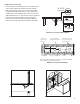
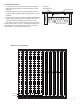
5. Install Tubing
• Pull one end of the tubing from the unwinder and feed through the
rstjoist.
• Create a large loop with the tube and feed the free end through the
adjacent joist.
• Make a small loop in each bay as you work towards the bay farthest
fromthemanifold.Pullenoughtubingtollthelastbay.Ifadditional
tubing is required, pull it from the loop in the previous bay. If too much
was pulled, push it back into the previous bay. Care should be taken
not to kink the tubing.
• Run the end of the tubing back to the manifold. Drill a return hole 8"
(203.2mm)awayfromtherst.
• Place the tubing into the fasteners. Begin by attaching the run of
tubing that is part of the return line going back to the manifold. This
sideoftheloopis“xed”.Theothersideisfreetofeedfromthe
unwinder and previous bays in case extra tubing is required.
• Always remember to place the tubing so bends have the largest
radius possible.
Inspection
After all the circuits are installed, take a few minutes to walk each
circuit and visually inspect the tubing for possible damage caused
during installation. If damage is found, repair it using an approved
Watts repair kit.
Pressure Test
Pressure test the system with 50-100 psi (3.4 - 6.9 bar) water or air for
24 hours. Do not use water if exterior temperatures are near or below
freezing (32.0°F (0.0ºC)) conditions.
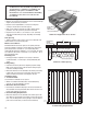
• Attach the pressure test kit to the manifold pair making certain
the rubber o-rings are properly seated before threading the
unions together.
• UsingtheSchraedervalveforairorthewaterllvalvesforliquid,
llthesystem(airorwater,butnotboth).
• Closethevalveandll.Pressuretestthesystemwith50-100psi
(3.4 - 6.9 bar) water or air for 24 hours.
Note: If the exterior temperatures are near or below
freezing (32.0°F (0.0ºC)) use air to pressure test.
If a fluid must be used, use a 50-50 water/glycol
solution. Failure to use glycol may result in frozen
circuits. The cool night air will usually cause less
than a 10 psi drop in pressure as the water or air
contracts from the cold.
Do not test over 100 psi (6.9 bar), as this will damage
the gauge on the test kit.
Some minor pressure changes will occur due to
the increased internal temperatures of the concrete
as it begins the curing process. Fluctuations in air
temperature may also cause a slight change in the
test pressure. In most cases, a 10-15 psi (0.7 - 1.0
bar) drop in pressure over a twenty four hour period
is not uncommon.
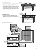
Manifold Pressure Test Kit and Connection Detail
Barb
Compression Ring
Compression Nut
Heating PEX or
Heating PEX-AL-PEX
Balance Valve
SupplyManifold
Mounting Bracket
AirTestGauge
Schrader
Valve
Return
Manifold
Vent/Purge
Drain
Drain
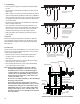
1. Pull a loop of tubing in the
rstjoistbay.
2. Continue to the next bay,
pulling from the previous
loop. Tubing will need to be
pulled from the unwinder
as well to keep enough of
aloopintherstbay.
3. Repeat for each
subsequent bay
4. Pull enough tubing to complete the last
bay using the loop in the previous bay as a
buffer for extra tubing.