
Installation guide


14
Under Floor Applications
• Minimizes the structural load requirements often associated with light
weight concrete (thin slab) construction.
• Requires no floor height additions, or removal of existing floor
coverings to install. Ideal for renovation projects.
• Make sure the tubing is installed in accordance with the design
parameters. If not, the system may not function as desired.
• Requires the use of either a 1" (25.4 mm) or a 1-3/4" (44.4 mm)
auger drill to install between joist bays, depending on how tubing
is installed.
Tube Spacing
• Tubing is installed 8" (203.2 mm) on center, to the underside of the
subfloor with the use of heat transfer plates.
Method of Installation
Extruded aluminum heat transfer plates are the primary fastening
method of installing an under floor system. Watts offers heat transfer
plates designed to be used with 1/2" (12.7 mm) Heating PEX or
Heating PEX-AL-PEX and are available in 4' (1.2 m) lengths. The plates
are installed 8" (203.2 mm) on center with a 2"-4" (50.8 mm - 101.6
mm) gap between plates.
Bend Supports
• Bend supports may be required if it is necessary to maintain a
certainbendradius,orifconnectingtoattingimmediatelyafter
a bend.
Pulling Tubing
• Install the heat transfer plates before beginning to pull the tubing.
Make sure the end of the plate is de-burred after cutting the plate
totbeforeinstallingthetubing.
• Measure the distance from the manifold to the farthest point moving
in right angles to ensure proper circuit length is being used. This
distance should be less than the circuit length for the zone.
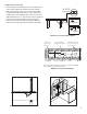
Installation Steps
1. Install manifolds.
Locate where the manifolds are to be placed.
• With the use of Watts manifold brackets or manifold mounting
enclosure, secure the manifolds to the wall.
2. Determine Zone Boundaries
• Before tubing is installed, visually inspect the area to determine the
zoneboundaries.Thishelpsdeterminewheretherstcircuitistobe
placed, while identifying any obstacles.
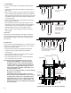
3. Confirm Tubing Requirements
• Measure the distance from the manifolds to the farthest point in the
zone. Make sure the minimum circuit length is at least twice this dis-
tance. If not, the tubing will not be long enough to reach the farthest
point of the zone and return (see slab section for illustration)
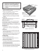
Return Manifold
Supply Manifold
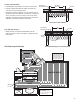
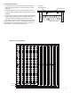
Under Floor Application Cross Section
Confirm Tubing Requirements
Under Floor Tube Spacing
8"
2” (50.8 mm) air gap
(203.2 mm)
Heating PEX or
Heating
PEX-AL-PEX
Heat Transfer Plate
Foil Faced Insulation
Heat Transfer
Plate
Heating PEX or
Heating
PEX-AL-PEX
Foil Faced Insulation
SubFloor
Note: Local building or plumbing codes may require
modifications to the information provided. You
are required to consult the local building and
plumbing codes prior to installation. If this
information is not consistent with local building
or plumbing codes, the local codes should
be followed.