Heating PEX and Heating PEX-AL-PEX INSTALLATION MANUAL
Contents WARNING ! General Handling & Storage 3 General Installation Cautions 3 Standards and Listings 4 Slab-on-grade Applications 5 Site Preparation 5 Insulation Requirements 5 Type of Insulation 5 Post Concrete Pour 5 Control Joints and Saw Cuts 5 Tube Spacing 6 Fasteners 6 Slab Profile and General Details 6 Installation Steps 6 Thin Slab over Frame Floor Applications 10 Tube Spacing 10 Fasteners 10 Thin Slab Profile 10 Installation Steps 10
Standards and Listings Heating PEX: – Heating PEX is manufactured to ASTM International (ASTM F876 and F877) and to SDR9 dimensions. These standards include requirements and testing methods for materials, workmanship, dimensions, environmental stress cracking, sustained hydrostatic pressure strength, bend strength, and degree of cross-linking. Heating PEX meets or exceeds these standards. – Heating PEX is tested and listed by the NSF International to NSF-14 (rfh).
Slab-on-grade Applications Slab • A common application consisting of any material or mass that encapsulates the radiant tubing, such as concrete, sand, or soil. Can be on or below grade. Site Preparation A radiant slab should always: Heating PEX or • Be placed on well drained base rock material. Heating • Be placed above an ample amount of crushed rock or gravel. PEX-AL-PEX Base Rock A radiant slab should never: Rewire or Rebar • Be placed directly on top of clay or organic subsoil.
Tube Spacing • R esidential slabs will use 6" (152.4 mm), 9" (228.6 mm), or 12" (304.8 mm) tube spacing with some perimeter banding. Banding is any area where the tubing is installed with a tighter on center spacing. Usually seen along exterior walls with higher than normal heat loss. 12 (304.8 mm) 9 • S pacing wider than 12" (304.8 mm) may produce unacceptable floor temperature variations (striping). Tube spacing wider than 12" on center is not recommended. (228.6 mm) 6 (152.
3. Determine Zone Boundaries Before tubing is installed, visually inspect the area to determine the zone boundaries. This helps determine where the first circuit is to be placed, while identifying any obstacles. 4. Confirm Tubing Requirements • M easure the distance from the manifolds to the farthest point in the zone via right angles. Slab • M ake sure the minimum circuit length is at least twice this distance.
6. Secure the Tubing • S ecure all bends and corners to prevent Heating PEX from curling, creating an unwanted high point in the circuit. • L eave 5' (1.52 m) slack on each circuit to allow adjustment of the manifold position from its temporary location. • T rim all “tails” of the cable ties to prevent any unwanted surface protrusions. • Keep all circuits within 10% of the same length. 8. Inspection • V isually inspect each circuit of tubing for possible damage caused during installation.
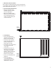
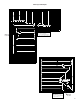
Slab Layout Examples Manifold Location Manifold Location 9
Note: L ocal building or plumbing codes may require modifications to the information provided. You are required to consult the local building and plumbing codes prior to installation. If this information is not consistent with local building or plumbing codes, the local codes should be followed.
2. Determine Zone Boundaries Before tubing is installed, visually inspect the area to determine the zone boundaries. This helps determine where the first circuit is to be placed, while identifying any obstacles. 3. Confirm Tubing Requirements Thin Slab • M easure the distance from the manifolds to the farthest point in the zone. 20 8 (6.3 m) • M ake sure the minimum circuit length is at least twice this distance.
5. Securing Tubing • When installing a thin slab over a subfloor, standard staples are used. Thin Slab • M ake sure the staple gun is set to 100 psi (6.9 bar) and does not come in contact with the tubing. Secure the tubing to the floor every 18"-24" (457.2 mm - 609.6 mm). • Try to keep all circuits within 10% of the same length. 6. Inspection • V isually inspect each circuit of tubing for possible damage caused during installation. If damage is found, repair it using an approved Watts repair kit.
Insulation Requirements Heating PEX or Heating PEX-AL-PEX • A standard paper faced insulation can be used in the joist cavity. 12" max (304.8 mm) Thin Slab • I nstall the insulation tight against the subfloor to minimize any convective losses that may be generated. • T he insulation should be a minimum of 3-1/2" (88.9 mm), or R-13, fiberglass batt when the radiant floor is installed over a heated space, such as a basement. 5-1/2"(139.
Note: L ocal building or plumbing codes may require modifications to the information provided. You are required to consult the local building and plumbing codes prior to installation. If this information is not consistent with local building or plumbing codes, the local codes should be followed. Sub Floor Heat Transfer Plate Under Floor Applications • M inimizes the structural load requirements often associated with light weight concrete (thin slab) construction.
4. Drill joists (if necessary) • D rill in accordance to structural requirements. To help keep the holes in line, it may be helpful to first mark the joists with a chalk line. Ø 1-3/4" (44.4 mm) • I f the supply and return sections of the circuit are to be installed through a common joist transition point, a 1-3/4" (44.4 mm) hole is required (option 1). If the supply and return sections are to be run in dedicated transition points, 1" (25.4 mm) holes can be used (option 2).
5. Install Tubing • P ull one end of the tubing from the unwinder and feed through the first joist. • C reate a large loop with the tube and feed the free end through the adjacent joist. 1. Pull a loop of tubing in the first joist bay. • M ake a small loop in each bay as you work towards the bay farthest from the manifold. Pull enough tubing to fill the last bay. If additional tubing is required, pull it from the loop in the previous bay. If too much was pulled, push it back into the previous bay.
Insulation Requirements • I t is important to have a tight seal between the horizontal insulation and the joist itself. The tighter the joist cavity, the better the system will perform. • F oil insulation will ensure most of the heat and energy coming from the tubing is reflected upward towards the subfloor where it is evenly distributed.. Heating PEX or Heating PEX-AL-PEX Heat Transfer Plate 2” (50.8 mm) • A 2-4" (50.8 -101.6 mm) air gap is necessary between the tubing and insulation.
HEATING PEX and Heating PEX-AL-PEX HEATING, COOLING, and SNOW MELTING LIMITED WARRANTY From Watts 1. Watts warrants its Heating PEX cross-linked polyethylene tubing, Heating PEX-AL-PEX cross-linked polyethylene/ aluminum/cross linked polyethylene tubing, fittings, and factory manufactured manifolds to be free of defects in material and workmanship when used in hydronic heating, cooling, and snow melting systems.
Materials and Tools Checklist √ Measuring Tape Chalk Line Electrical Tape Marker Electric Drill 1-3/4" (44.