
Instructions / Assembly
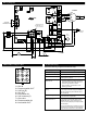

Wiring Diagram
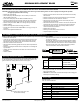
ICM280 Molex Plug Pin Out Trouble Shooting
FORM-C
NC
NO
C
C
COIL
C
NO
NC
C
NO
NC
C
NO
NC
F1
COOL
HEAT
M1
M2
HSI
IND
L2
PRI TRANS
NEUTRALS
FS
ATO 3A
W
G
R
STATUS
TWIN
90+O
90+I
N/U
FS
GV
PSO
PSI
LIMO
LIMI
P1
FORM-C
NC
NO
C
C
COIL
CON2
23
456
1
89 7
HEAT
DELAY
BLK
120
90
150
115V HUM
EAC
24V HUM
ICM280
ICM280
TEST
PS
LPS
HI
MH
COM
BLOWER
CAP
BRN
BRN
ML
LO
HOT SURFACE
IGNITOR
VENT
MOTOR
115V
24V
XFMR
115VAC SUPPLY
FLAME
SENSOR
TO ROOM
THERMOSTAT
GAS VALVE
JUMPER NECESSARY
BETWEEN PINS 1 & 4
FOR 90+ SELECTION
1 = 90+ IN
2 = Pressure switch OUT
3 = 24V hot (R)
4 = 90+ OUT
5 = Limit switch IN
6 = 24V common (C)
7 = Gas valve
8 = Pressure switch IN
9 = Limit switch OUT
Should be done by competent technician only.
Symptom Remedy
Fault light is blinking Check status led chart to determine problem
Blower fan runs constantly Check for open limit
No ame Check hot surface ignitor, verify voltage to hot
surface ignitor is present
Furnace turns off when gas
valve turns on
1. Verify pressure switch is not opening, test
by placing temporary jumper across pres-
sure switch when inducer fan turns on to
simulate a good pressure switch.
2. Verify secondary of transformer is ad-
equately grounded.
Furnace turns on and off
rapidly
Verify thermostat is functioning correctly, test
by removing thermostat wiring from ICM280
and placing temporary short between the R
and W terminals
Flame not being sensed Verify ame sense rod is clean, verify second-
ary of transformer is grounded
Furnace turns off when
blower fan turns on
Verify thermostat is functioning correctly, test
by removing the thermostat wiring from the
ICM280 and place jumper from R to W. If
furnace functions properly then replace defec-
tive thermostat.
If furnace still functions incorrectly then check
the wiring of the secondary of the transformer,
swap connections at R and C at the ICM280.