
User's Manual


2
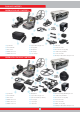
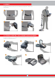
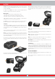
ASSEMBLY
(1) Insert the washers on the lower shaft yoke.
(2) Insert the lower shaft yoke between search coil mount tabs.
(3) Attach the search coil to the lower shaft using the lever, winged nut and the
washer without over-tightening.
(4) Fully insert the middle shaft into the lower shaft and push it until it contacts the
stopper. Then, secure with the lever latch. If the lower shaft is not inserted fully, the
connector at the end of the cable will not come out from the top of the shaft in the
next step.
(5) Insert the search coil cable through the shaft as shown in the picture.
(6) Pull the lever latch of the IPTU sensor, attach it to the shaft in the direction shown
in the picture and push it until the shaft's latch. Then, push the latch to secure.
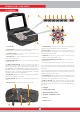
(7) Join the two connectors of the system box cable and coil cable paying attention
to the pins, then tighten. The system box cable is a retractable spiral and you can
pull it in case you cannot join the two connectors easily.
(8) Join the middle and the upper shafts. Pull the excess cable out of the hole and
push the lever latch on the upper shaft to secure. To adjust the shaft length, loosen
the lever latch on the middle shaft, adjust the length to your height and press the
latch to secure.
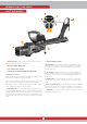
(9) Insert the connector of the IPTU connection cable into the socket on the sensor
and secure by tightening the nut. While tightening, you will hear clicks. This is normal
and indicates that the connector is locked in.
(10) Wind the sensor connection cable on the shaft without stretching too much.
Then, plug the connector to the socket on the system box and secure by tightening
the nut.
(11) To adjust the armrest, loosen the bolts. Slide the armrest up and down to adjust
it to your arm and secure by tightening the bolts.
(12) Adjust the armrest strap to your comfort.
The assembly is now completed. You can start using the device after completion of
the IPTU sensor assembly explained in the next section.
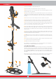
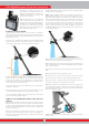
IPTU SENSOR ASSEMBLY
The angle of the sensor must be adjusted according to the type of coil attached to
the device. In order to do this, the blue or the red line on the sticker located on the
sensor must be aligned with the blue or red line on the sensor's lever latch. The red
line is for INV28 and INV40 search coils and the blue line is for the INV56 search
coil. Improper adjustment of the sensor angle will result in inaccurate operation of
the sensor.
Details about the usage of the IPTU sensor and the things you must pay attention
to are further explained in the manual. Please read those sections carefully!
1
12
3
2
4
8
9
10
5
6
11
7