
User's Manual


25
Please read the following section very carefully before operating the
device. This is important in terms of getting the best performance out
of your detector!
WIRELESS CONNECTION AND PAIRING
The INVENIO system box and shaft & handle communicate wirelessly.
Normally, the system box and the shaft & handle are paired before they
are shipped from the factory. Therefore, they will connect directly upon
initial start up.
Please follow the pairing steps below if there is no connection
established :
1. Be sure that the system box and shaft & handle are turned off.
2. While pressing the SCAN button on the handle, turn the ON/OFF
switch on the shaft to ON position. The LED on the handle will start
blinking red.
3. While pressing the Zoom In button on the system box, turn the
system box on - do not let go of the button! When the pairing is
successful, the LED will blink green twice and turn off. You can now
let go of the button.
4. Once the pairing is done, the system box and shaft & handle will
connect automatically upon start up.
NOTE : You may hear the sound of the relay circuit in the shaft during
pairing; this is normal.
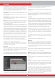
You can follow the status of the wireless connection from the 2.4G
icon the INFO bar located at the bottom of the screen. If the icon is
green, it means there is connection. If the icon is red, it means there
is no connection.
If the Wireless Shaft Channel is turned off in the OPTIONS, the
connection will be lost, the LED on the handle will start blinking red
and the 2.4G icon on the INFO bar will turn red as well.
Similarly, if the connection is lost due to any reason, the LED on the
handle will start blinking red. When the connection is reestablished,
the LED will blink green twice.
SEARCHING
All modes of the INVENIO, except for the Ground Anomaly & Cavity,
work in 2 different detection screens - one with and one without the
IPTU sensor. The Ground Anomaly & Cavity mode will work in the
detection screen with the sensor only. Detection screen selection
does not have direct effect on the operation of the modes. The main
difference between the 2 screens is as follows: When searching in the
detection screen without the IPTU sensor, the device detects targets
and displays their IDs only. On the other hand, while searching in the
detection screen with the IPTU sensor, apart from the IDs, the device
also provides the instant depth, shape and 3D graphs of detected
targets.
SEARCHING IN DETECTION SCREEN WITH IPTU SENSOR
A. SENSOR CALIBRATION
1. First, adjust the shaft length and coil angle to searching position.
Then place the search coil on a flat surface, adjust the search coil angle
so that it is parallel with the ground and lean it against a fixed object
such as a tree, rock or a wall. If there is no place to lean it against, hold
it stable with your hand.
2. Turn both the system box and shaft & handle on.
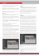
3. Press the SETTINGS button and select ''Calibrate the sensor''.
4. Press the OK button and wait for the calibration process to be
completed. Once the progress bar is full, the calibration will be
completed and the device will automatically revert to the selected
mode's detection screen.
NOTE : If you will search using the detection screen without the IPTU
sensor, you do not need to do the calibration process.
B. GROUND BALANCE
Especially if you will use one of the non-motion modes, you must
ground balance the detector before starting to search. Ground
balancing plays a big role in minimizing the false signals and obtaining
target shapes. All details regarding ground balance are explained in
the relevant sections of the manual.
C. SEARCHING
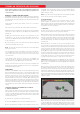
To obtain accurate data in the detection screen with the IPTU sensor,
first be sure that the IPTU sensor is properly calibrated.
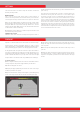
While searching in this screen, the height of the coil above the ground
is critical for the sensor to obtain accurate data. For this reason, pay
attention to the height indicator on the screen. The ideal search height
is shown with green on the indicator. To obtain the best results while
searching and scanning, pay attention to keeping the search coil within
the green area.
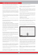
While searching in this screen, you can see the movements of the
coil in real time on the 3D detection ground. As the search coil moves
forward or back, the 3D detection ground will slide. The areas scanned
over by the search coil will be painted in gray on the screen. You can
see how much area you have scanned by zooming in and out on the
ground. When you zoom in or out on the ground, the target signals and
the search coil will also be zoomed in or out. Zoom does not affect the
scaling of the ground. For example, if the search coil scans an area of
1 meter while you zoom in or out on the ground at maximum, the total
scanned area will still be shown as 1 meter on the result screen.
TRACE function : When you press the TRACE button and activate this
function, the screen will follow the coil and rotate in the same direction.
When you press the TRACE button, the word TRACE will be displayed
on the INFO bar.
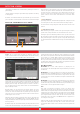
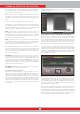
When you detect a target in the detection screen with the IPTU sensor,
the target ID will be displayed on the cursor on the color ID bar at
the top of the screen. At the same time, the signal obtained from the
target will be displayed with a 3D graph and colored according to the
type of target. Ferrous metals are indicated with red, gold/non-ferrous
metals with yellow, and non-ferrous metals are indicated with green. In
addition, the depth of the detected target will be shown on the depth
indicator instantly.
While searching in this screen, drifts may happen in both directions
on the Drift-Metal bar at the bottom. When the bar fills up in the Drift
direction, nothing will be displayed on the 3D detection ground, and the
device will not produce any audio. When the drift happens in the metal
TURNING ON THE DEVICE AND SEARCHING