
User's Manual


22
DETECTION SCREENS
HEDEF ID
measurement plays an important role for the device to eliminate the
false signals produced by these rocks.
Magnetic Mineralization Indicator will be displayed on screen in all
modes except for the Ground Anomaly & Cavity mode. You can remove
it by pressing the INFO button. It will come back on screen when you
press the INFO button again.
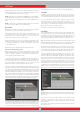
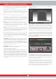
(3) Ground Balance Window
The ground balance window is divided into 2 parts: The top part shows
the instant ground balance value changes while searching and the
bottom part shows the adjusted ground balance value.
Ground Balance window will be displayed on screen in all modes except
for the Ground Anomaly & Cavity mode. You can remove it by pressing
the INFO button. It will come back on screen when you press the INFO
button again.
To learn how to ground balance the INVENIO, please read the section
titled ''Ground Balance''.
(4) Height Indicator
Shows the height of the search coil on the bar, in centimeters or inches.
The ideal search height for the type of search coil attached, is indicated
with green color. If you hold the search coil at a different height than
the recommended one, this will be indicated by red color on the bar.
(5) Depth Indicator
Shows the depth of the detected target, in centimeters or inches.
It ranges between 0 to 150+ (0-60+ in inches). In other words, for
depths greater than 150cms (60'')., it will show 150+ (60+ in inches).
Upon target detection, the bar will rise and the target depth will be
indicated numerically. Depth reading may vary based on target size
and orientation, metal type and ground conditions.
IMPORTANT! To see the target depth instantly in non-motion modes,
you need to swing the search coil more slowly.
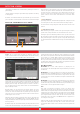
(6) Drift - Metal bar
This bar is present only in the Basic and Expert modes.
All signals obtained by the device, as well as drifts, while searching, are
shown on this bar.
Changes in the ground and temperature, as well as environmental noise,
may lead to negative and positive drifts. During negative drifts, the bar
will fill up in the DRIFT direction, in proportion to the strength of the
drift.
When the device detects a metal or a positive hot rock or if a positive
drift occurs, the bar this time will fill up in the METAL direction, again
in proportion to the strength of the signal or the drift.
(7) Zoom
It is used to magnify or reduce target signal graphs. By using this
feature, you can magnify smaller signal graphs and reduce the larger
ones to better examine them.
If you wish, you can change the zoom scale with the up and down
buttons.
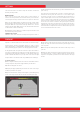
(8) 3D Detection Ground
During searching you can observe the following on the 3D detection
ground :
* All movements of the search coil - left, right, up and down,
* The total scanned area,
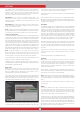
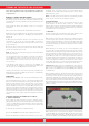
INVENIO has 2 detection screens: One with, and one without the
IPTU sensor. The screen with the sensor, will only function fully, when
the IPTU sensor is attached to the device, and it is turned on. If the
detection screen with the sensor is used while the sensor is not
turned on, the device will detect targets and provide their IDs, however
the advanced features (explained further in the manual) will not work.
The detection screen without the IPTU sensor on the other hand, can
always be used, regardless of whether the sensor is attached or not.
All modes, except for the Ground Anomaly & Cavity, will work in
both screens. The Ground Anomaly & Cavity mode will work in the
detection screen with the sensor only. Detection screen selection
does not have direct effect on the operation of the modes. The main
difference between the 2 screens is as follows: When searching in the
detection screen without the IPTU sensor, the device detects targets
and displays their IDs only. On the other hand, while searching in the
detection screen with the IPTU sensor, apart from the IDs, the device
also provides the instant depth, shape and 3D graphs of detected
targets.
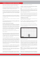
DETECTION SCREEN WITH IPTU SENSOR
(1)
Target ID Scale
Ranging from 0 to 99, this scale indicates which metal group the ID of
the detected target falls in. Each metal group is indicated by a different
color. For example, negative hot rocks and soil are shown by white
and brown colors, ferrous metals, such as iron, by red, and gold and
non-ferrous metals are indicated by yellow and green colors. When a
target is detected, the cursor will point to the target ID on the scale.
The IDs filtered by Discrimination and Notch Filter settings are shown
in black color on this scale. For more information please read the
sections about Target ID and Notch Filter.
(2) Magnetic Mineralization Indicator
Magnetic Mineralization Indicator ranges from 0 to 99. Upon start up,
the indicator will be empty and 0 will be displayed inside. Based on
the level of magnetic mineralization, this chart will fill up yellow and
the mineralization level will also be indicated numerically inside the
chart.
This measurement can be summarized as the level of magnetic
property and intensity of the ground. Simply, if you are working in an
area which contains intense and magnetized minerals, the level will
be high. If you are working on a less intense ground, the level will be
low.
This measurement is important from two aspects. First, on grounds
with high magnetic mineralization, search depth is low and users
should be aware of this fact. Second, magnetic mineralization is a
property which is particularly seen with mineralized rocks and this
12
4 7 86 5
3