FCC ID: 2AJJ2-INVENIOBOX INVENIO INVENIO PRO INVENIO LITE
WARNINGS READ CAREFULLY BEFORE OPERATION OF THE DEVICE LEGAL DISCLAIMERS Ź Comply with applicable laws and regulations governing use of metal detectors while using this detector. Do not use the detector without authorization in protected or archeological sites. Do not use this detector around unexploded ordnance or in restricted military zones without authorization. Notify appropriate authorities with details of any historical or culturally significant artifacts you find.
TABLE OF CONTENTS PACKAGE CONTENTS ....................................................................................................................................................................................................................... 1 ASSEMBLY..........................................................................................................................................................................................................................................................
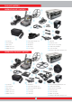
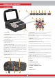
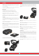
PACKAGE CONTENTS INVENIO PACKAGE CONTENTS (1) System Box (2) Shaft & Handle (3) IPTU Sensor (4) INV40 Search Coil (5) INV28 Search Coil (6) System Box Carrying Case (7) Carrying Belt (8) Headphones (9) AC Charger (10) Car Charger (11) USB Cable (12) Protective Covers (13) IPTU Sensor Carrying Bag (14) Coil Mounting Hardware (15) Screen Sunshade (16) Waterproof (IP67) Hard Transport Case INVENIO PRO PACKAGE CONTENTS (1) System Box (2) Shaft & Handle (3) IPTU Sensor (4) INV40 Search Coil (5) INV56 Search
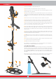
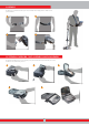
ASSEMBLY (1) Insert the washers on the lower shaft yoke. (2) Insert the lower shaft yoke between search coil mount tabs. (3) Attach the search coil to the lower shaft using the lever, winged nut and the washer without over-tightening. 12 (4) Fully insert the middle shaft into the lower shaft and push it until it contacts the stopper. Then, secure with the lever latch.
ASSEMBLY To wear the system box around your neck, assemble the carrying belt as shown in the pictures below. 1 2 3 4 SYSTEM BOX CARRYING CASE ASSEMBLY AND DISASSEMBLY To take the system box out of its carrying case, please follow the steps below. To put it back inside the case, reverse the process.
INTRODUCTION TO THE DEVICE SYSTEM BOX 1 2 a b c d e f g SETTINGS TRACE PAN ROTATE SCREEN CAPTURE INFO OPTIONS ON / OFF 3 a c BACK b OK c c e 4 (1) LCD SCREEN c d (3) LOWER KEYPAD - The functions of the buttons on this keypad are explained further in the relevant sections of the manual. (2) UPPER KEYPAD - The functions of the buttons on this keypad are a) BACK BUTTON : It allows you to exit the current screen or to go back to the previous one.
INTRODUCTION TO THE DEVICE SHAFT AND HANDLE d 6 a 5 CLR BACK SCAN OK b e c 4 1 2 3 (1) ON/OFF BUTTON : It powers the shaft and handle on and off. It works independently from the system box. (6) SHAFT & HANDLE KEYPAD a) BACK BUTTON : It has the same function as the BACK button on the system box. It allows you to exit the current screen or to go back to the previous one. In addition, it is used to remove the pop-up message windows from screen.
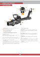
IPTU SENSOR (Integrated Positional Tracking Unit) 3) The location and the angle of the sensor must be adjusted properly according to the coil being used. The IPTU unit, with the help of the integrated sensors, computes the right-left, forward-back movements of the search coil precisely and determines its location and height above the ground. NOTE : When the INV56 search coil is attached to the device, the message ''Attach the sensor to the 2nd hole!'' will appear on screen.
BATTERY INVENIO works with 2 lithium polymer batteries. One of these is located inside the system box (5500mAh) and the other one is at the back of the shaft (5400mAh). After removing the battery, plug the charger into the charging socket on the battery. After charging is completed, insert the battery back in the compartment and close the cover. Be sure that the tabs sit securely in place. In addition, the INVENIO Pro includes a spare 9500mAh battery providing a longer battery life for the system box.
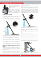
CORRECT USE Shaft height is wrong Shaft height is correct It is very important to adjust the shaft to your height correctly to be able to search without discomfort and fatigue. Adjust the height of the shaft so that you are standing in an upright position, your arm is relaxed and the search coil is approximately 5cm (~2'') above the ground.
INFO BAR Refresh GB! This message will appear under the following situations: When the operating frequency is changed (only in INVENIO Pro), when the sensitivity level is changed or when the mode settings are restored to factory defaults. It indicates that you should re-ground balance the device. Once you ground balance, the message disappears. Calibrate the sensor! It comes up on screen at initial start up or when you switch to the detection screen with the IPTU sensor.
GROUND BALANCE 5) When the ground balance trigger is released, the device continues to operate in the All Metal mode for a short period of time and the ground balance window stays on screen. The word ''Manual'' will appear bigger on screen. This makes it possible to manually fine tune the automatic ground balance value. Refer to the following "Manual Ground Balance" section for further information regarding this feature.
GROUND BALANCE In this option, the user does not need to make any adjustments. Tracking feature is activated by selecting it from the settings of the motion modes and by switching it to on position. The word ''Tracking'' will be displayed in green at the bottom of the ground balance window. The device updates the ground balance automatically as long as the search coil is swung over the ground and shows the ground balance value in the ground balance window.
GROUND BALANCE 5) When using the optional large coil, pump the coil more slowly and do not keep it very close to the ground. You cannot search in the All Metal and Non-Motion modes (except for the Ground Anomaly & Cavity) without ground balancing. You need to use one of the discrimination modes and increase the Discrimination value until the noise is eliminated. 4) Once the ground balance is set, it will remain satisfactory for a long time in most areas.
OPTIONS OTHERS SOFTWARE UPDATE in the static modes only in case of overload. When vibration is active, the vibration icon on the INFO bar will turn green, when vibration is disabled, it will turn red. This option shows the software version installed on your device and it also enables you to update your device. All software updates for the INVENIO will be published on the product page at www.noktadetectors.com. You can follow all updates and instructions from this page.
OPTIONS under this folder. Result screens are filed in chronological order. Graphs saved on the same date are numbered and filed in the same folder. Graphs saved on different dates are filed and listed according to the date they were saved on. In the folder view, next to the folder, you can see the date and number of records in the folder. When 3D files are selected, to select a folder, press the plus (+) button. The selection box will move to the adjacent section.
OPTIONS DELETING THE ARCHIVES FILES AND SAVING You can delete multiple or individual files in the archives or save them to a USB drive. To delete individual files : Using the plus button (+), select the small box next to the file or folder. The box will turn orange. When you press the OK button, a check mark will appear in the box and the line will appear blurred. Click the trashcan icon next to the box and press OK.
SETTINGS release it to manually retune the device. If the drifts still continue frequently, drop the sensitivity gradually and re-ground balance. Sensitivity in Expert Mode : In cases where you want to change the sensitivity setting (sudden changes in weather conditions, different ground structures or environmental noise) first re-ground balance. If there are many negative or positive drifts after re-ground balancing, pull the trigger towards you once and release it to manually retune the device.
SETTINGS TIP : If the signal detected with the subthreshold setting is large and you can increase the sensitivity level, you can take the signal over the threshold level and make it audible by increasing the sensitivity for an instant. This way you can check the signal and see what kind of a target it is. other than the ones you want to ignore, may also be missed or their signals may become weaker when using the discrimination setting.
SETTINGS not available in this screen. Therefore, you can set the Stabilizer to maximum levels to get rid of the drifts but keep in mind that as the Stabilizer is increased, the device may detect weaker signals but will not be able to detect the targets anymore if you hold the coil stationary or sweep back and forth over the target. cursor will turn orange. Then, press the OK button and using the plus (+) and minus (-) buttons again, adjust the frequency.
SETTINGS turn orange and the notched out number on screen will disappear. At the maximum level of iMask false signals will disappear or will be minimized. However, in some cases, increasing the iMask will result in loss of depth for certain metals such as copper. Iron Audio It adjusts or turns off the volume of the low iron tone. It consists of 5 levels adjustable with the plus (+) and minus (-) buttons. Factory default is the maximum level. The adjusted level is indicated with orange color.
SETTINGS provide accurate data. For this reason, you must calibrate the sensor upon start up. Save function works in all modes except for the Basic and Ground Anomaly & Cavity modes. First, adjust the shaft length and coil angle to searching position. To calibrate the sensor, place the search coil on a flat surface, adjust the search coil angle so that it is parallel with the ground and lean it against a fixed object such as a tree, rock or a wall.
DETECTION SCREENS measurement plays an important role for the device to eliminate the false signals produced by these rocks. INVENIO has 2 detection screens: One with, and one without the IPTU sensor. The screen with the sensor, will only function fully, when the IPTU sensor is attached to the device, and it is turned on.
DETECTION SCREENS * The length and width of the scanned area by zooming in and out on ground image, The functions of the target ID scale, the magnetic mineralization indicator, the ground balance window, and the Drift-Metal bar are the same as those in the detection screen with the IPTU sensor. For this reason, these are not explained again in this section. If you wish, please read the section above titled ''Detection Screen with IPTU Sensor''.
SEARCH MODES The threshold in this mode is internal and cannot be adjusted by the user. Changes in the ground and temperature may lead to drifts in the threshold. Threshold drifts will be reflected in the bar at the bottom either in the negative way (in the DRIFT direction) or the positive way (in the METAL direction). The device emits an audible response in the positive drifts and shows the target signal.
TURNING ON THE DEVICE AND SEARCHING Please read the following section very carefully before operating the device. This is important in terms of getting the best performance out of your detector! completed. Once the progress bar is full, the calibration will be completed and the device will automatically revert to the selected mode's detection screen. WIRELESS CONNECTION AND PAIRING NOTE : If you will search using the detection screen without the IPTU sensor, you do not need to do the calibration process.
TURNING ON THE DEVICE AND SEARCHING needed, you can zoom in and out on the screen. direction on the other hand, a flat, continuous graph will appear on the detection ground, and the device will produce an audio response. If a metal or a positive hot rock is detected, the target ID will be displayed on the ID bar at the top. The target ID bar in this mode is white and not colored like the other modes. In such a case, pull the trigger towards you once and release it to manually retune the device.
TURNING ON THE DEVICE AND SEARCHING The sample image below belongs to a result screen of a 200x250cm. (6.7'x8.3') scanned area. painting will be in red or blue for a short period of time independent from the target. Then the painting will be done according to the metal type just like in the search screen.
RESULT SCREEN When you are on the last target, if you press the OK button again, you can see the start and finish points of the scan as well as all the movements of the coil drawn linearly. The INVENIO allows the user to view the 3D graphs of the detected targets and analyze them.
RESULT SCREEN options and the word ''Saved'' will be displayed in green at the bottom of the dashboard. This is the initial top view: NOTE : You can open the 3D graphs you saved in the ARCHIVES and perform all the functions above, later as well. (4) DELETE Once the result screen is saved, ''Delete'' will be displayed instead of ''Save'' under 3D GRAPH OPTIONS. When delete is selected, the warning message ''Are you sure you want to delete the data?'' as well as the record number will appear on screen.
ARTIFICIAL INTELLIGENCE AND NEURAL NETWORK 6. Then, press the down button and select the target. The target will be marked in green. INVENIO is the world's first metal detector using artificial intelligence and artificial neural network.
This equipment has been tested and found to comply with the limits for a Class B digital device, pursuant to part 15 of the FCC Rules. These limits are designed to provide reasonable protection against harmful interference in a residential installation. This equipment generates, uses and can radiate radio frequency energy and, if not installed and used in accordance with the instructions, may cause harmful interference to radio communications.