Product Overview Ethernet bridge adapters 100BASE-T, E66210.32 10/100BASE-T, E66210.
Product Overview The information in this document is subject to change without notice and describes only the product defined in the introduction of this documentation. This document is intended for the use of Nokia's customers only for the purposes of the agreement under which the document is submitted, and no part of it may be reproduced or transmitted in any form or means without the prior written permission of Nokia.
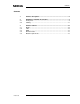
Contents Contents DN0610789 1 Product description ...............................................................................4 2 2.1 2.2 Hardware installation instructions .......................................................7 Front panel ...............................................................................................9 Cabling ...................................................................................................11 3 3.1 3.2 3.3 3.4 3.5 Product features..............
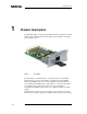
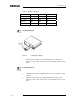
Product Overview 1 Product description The Nokia ET-adapter is a plug-and-play Ethernet interface adapter for Dynanet (DNT) modems. This Ethernet interface adapter can be installed to the adapter port of a DNT modem. Figure 1. ET adapter The main function of the ET-adapter is to bridge two LANs over the WAN. Ethernet frames received from the LAN are encapsulated inside the HDLC frames and the HDLC frames are sent to the WAN according the serial data speed of WAN.
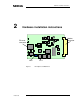
Product description are fixed. There are three selectable Ethernet interface settings in E66210.33: 10BASE half and full duplex and 100BASE full duplex. The data path and main components of ET-adapter are described in the block diagram below. WAN Power 3,3V / 1,8V ISEPROM 2048x8 HDLC Bridge DS33ZII Euro ET-Adapter 100 BASE-T MII PHY LXT971 10/100 RJ-45 Link integrity & activity LAN LEDs SDRMA 4x1Mx32 Figure 2. Block diagram ET-adapter is compatible to virtual LANs and 802.
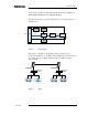
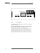
Product Overview Ethernet bridge adapter makes rate adaption and it can be connected to 10BASE-T ET-adapter or DYNANET EIU. 100BASE-T 10BASE-T Figure 4. 10BASE-T E66210.
Hardware installation instructions 2 Hardware installation instructions Modern connector Ethernet connector NR3 Figure 6. DN0610789 Pin 1 ET Adapter card E66210.
Product Overview Table 1. E66210.33 bridging Link speed 10BASE 10BASE 100BASE Duplex status Half Full Full Closed pins 1-2 3-4 5-6 LED 100 Off Off On LED HD On Off Off Installing E66210.32 Figure 7. 1. Installing the adapter Switch off the modem power, plug the ET-adapter into the slot and tighten two screws. Then switch on the modem. The ET-adapter is ready to use. Installing E66210.33 8 (14) 1. Select Ethernet interface configuration and close pins of NR3 according to Table 1.
Hardware installation instructions 2.1 Front panel 100 BASE-T Bridge RX Figure 8. LINK Front panel RX displays receive status: LED blinks every time when an Ethernet packet is received from the LAN. LINK displays link status: LED is lit when cable is connected to another Ethernet equipment and the link is up. Link status is also shown at the DNT modem: if the link is down there is no incoming signal alarm.
Product Overview Speed Duplex Half 100 Full 100 Full 10/100 BASE-T Bridge 10 RX Figure 9. LINK 100 100 Off Off On HD On Off Off HD Front panel E66210.33 RX displays receive status. LED blinks every time when an Ethernet packet is received from the LAN. LINK displays link status. LED is lit when cable is connected to another Ethernet equipment and the link is up. Link status is also shown at the DNT modem: if the link is down there is no incoming signal alarm. 100 displays speed status.
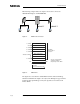
Hardware installation instructions Figure 10. 2.2 Pin Signal Direction 1 Rx+ input 2 Rx- input 3 Tx+ output 4 Not connected 5 Not connected 6 Tx- 7 Not connected 8 Not connected output Ethernet connector and pin numbering Cabling ET-adapter is connected to the network adapter with a direct Ethernet cable. The maximum length of a category 5 cable is 100m. If the ET-adapter is connected to the Ethernet hub or switch then use a cross-connected Ethernet cable. Figure 11.
Product Overview 3 Product features 3.1 Bridge All received frames are forwared transparently to the WAN. Receive buffer size 1728 MAC frames Transmit buffer size 320 MAC frames Receive buffer is queue for data that was received from the Ethernet (LAN) to be transmitted to the HDLC (WAN). Transmit buffer is for data that was received from the WAN to be transmitted to the Ethernet.
Product features Maximum transfer unit 2016 bytes Any frame larger than the maximum transfer unit (MTU) value will be rejected. The frame size includes destination address, source address, type, length, data and CRC. Standard Ethernet frame maximum length is 1518 bytes (destination address 6 bytes + source address 6 bytes + type 2 bytes + data 1500 bytes + CRC 4 bytes). Cable 3.
Product Overview 14 (14) DNT2M-sp T65620 DNT2M-mp T65630 DNT2Mi-sp T65670 DNT2Mi-mp T65680 DNT2M-G-sp T65650 DNT2M-G-mp T65660 © Nokia Corporation DN0610789