REMOTE I/O CONTROL GUIDE Copyright © 2002-2004 Nokia. All rights reserved. NOKIA 12 GSM MODULE Issue 2.
Contents ACRONYMS AND TERMS ...................................................................................................... 1 1. ABOUT THIS DOCUMENT ................................................................................................ 2 2. INTRODUCTION ................................................................................................................ 3 2.1 GENERAL...................................................................................................................
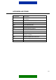
9.3.4 Reading Outputs.................................................................................................. 34 9.3.5 Writing Outputs .................................................................................................... 35 9.3.6 Inverting Outputs ................................................................................................. 37 9.3.7 Output Pulses ...................................................................................................... 38 9.3.
Legal Notice Copyright © 2002-2004 Nokia. All rights reserved. Reproduction, transfer, distribution or storage of part or all of the contents in this document in any form without the prior written permission of Nokia is prohibited. Nokia and Nokia Connecting People are registered trademarks of Nokia Corporation.
ACRONYMS AND TERMS Acronym/term Description ASCII American Standard Code for Information Interchange AT Attention CORBA Common Object Request Broker Architecture CSD Circuit Switched Data GPRS General Packet Radio Service GPS Global Positioning System GSM Global System for Mobile Communications I/O Input/Output M2M Machine-to-Machine, Mobile-to-Machine, Machine-to-Mobile NITZ Network Indication and Time zone SMS Short Message Service SW Software 1/49
1. ABOUT THIS DOCUMENT This document describes how the Nokia 12 GSM module can be used in Remote I/O control mode. The methods for controlling a module in this operation mode are described, as well as how to increase security. Before using the product, it is important to read the safety instructions and notifications at the end of this document, see chapter 10.
2. INTRODUCTION 2.1 GENERAL The Nokia 12 GSM Module provides wireless connectivity and remote management possibilities for machine-to-machine (M2M) applications and other wireless solutions. The Nokia 12 GSM Module has two variants: • RX-2 is dual band EGSM900/GSM1800 product • RX-9 dual band GSM850/GSM1900 product. The Nokia 12 GSM Module supports EGPRS, GPRS, HSCSD (not supported in RX-9), CSD, and SMS.
Monitor a device Find out if a device is already on or off Receive alarm messages if a device has been switched on or off Receive alarm messages if a specified alarm limit has been crossed Personalize Define your own device commands (aliases) Disable acknowledgements for device commands Select the frequency of alarm messages (alarm once/continuously) Identify the calling party and give permissions for device control Position Get position information through the Nokia 12 GSM Module when connected to a G
3. SECURITY There are different levels of access control for the Remote I/O control: message identifier, password, and authorised numbers. Also the aliases defined for commands increase security. You must use a message identifier, which means that you must name the Nokia 12 GSM Module to be able to use the Remote I/O control. Each control message begins with an identifier, which enables the Nokia 12 GSM Module recognise it as a Remote I/O control message.
6/49
4. GETTING STARTED 4.1 SETTING UP THE CONFIGURATOR ENVIRONMENT To use Configurator, the following tools are needed: • Nokia 12 GSM Module (RX-2 or RX-9) • Nokia 12 test board • Power supply ACW-6 • Data cable AXS-3 • Antenna adapter cable • Antenna • SIM card All items listed above, except the SIM card, are included in Test board sales package. Configurator can be used with a SIM card inserted to the test board SIM card holder. To use Configurator: 1.
When you have completed the above steps, Configurator automatically establishes a connection between the PC and the Nokia 12 GSM Module when Configurator is started. 4.2 CONNECTING A DEVICE OR A MACHINE Connect the device to be controlled with the Remote I/O control to the Nokia 12 GSM Module through the M2M system interface. The general-purpose inputs and outputs of the M2M system connector that are described in Chapter 6 are connected to the device.
4.4 READING AND WRITING PARAMETERS To read parameter values from the Nokia 12 GSM Module and write parameter values to it, use Configurator. Each Configurator dialog has “Read parameters” and “Write parameters” button for this purpose. Data is transferred between Configurator and the Nokia 12 GSM Module only after you have clicked either of these buttons. Note: To apply the configured settings, click either the Read parameters or Write parameters button.
Characters accepted for the message identifier are defined in Chapter 7, except the space characters. Note: You cannot use the Remote I/O control if there is no message identifier defined. In this case, all received short messages will be handled as normal messages and the inputs/outputs cannot be controlled in the Remote I/O control. Note: The message identifier is 1-8 characters long and case sensitive. Figure 2.
4.6 SETTING THE SMS CENTRE ADDRESS A dialog for setting the SMS centre address with the Nokia 12 Configurator (GSM Settings -> Advanced -> Short Messages) is shown in Figure 3. To check whether the SMS centre address is available on the network service provider SIM card, press the Read parameters button shown in Figure 3. If the SMS centre address is not available, specify it in the Short Messages dialog in order to be able to use the Remote I/O control.
SIM card and the Nokia 12 GSM Module memory are full. It is recommended to select the option “Remove oldest message when new arrives” for the Remote I/O control, because then the control messages have a better chance of reaching their destination and fulfilling their purpose.
5. OPTIONAL CONFIGURATIONS 5.1 DISABLING ACKNOWLEDGEMENTS The Nokia 12 GSM Module acknowledges whether or not a text message has successfully commanded a device. The Nokia 12 GSM Module sends a response as a text message back to the phone number that sent the control message. It is also possible to disable this feature to decrease the amount of communication with the device, for example. Figure 4 displays a dialog (User Control Mode -> Settings -> General) for configuring acknowledgement messages.
Figure 4. General settings If you select the Disable acknowledgements option, only response messages to acknowledgement messages are disabled. The following will not be disabled: • Status messages; responses to input state or value queries • Indication messages, for example, responses to timed commands (see Chapter 9.3.7) • Alarm messages; responses to alarm subscriptions (see Chapters 5.4 and 9.3.
5.2 • Response messages to password change messages (see Chapter 9.3.1) • Response messages to pulse cancel messages (see Chapter 9.3.8) SECURITY SETTINGS Figure 5 shows a dialog (User Control Mode -> Settings -> Security) where security settings can be configured with Nokia 12 Configurator. 5.2.1 Authorised numbers Authorised number selection limits the access to specific phone numbers only in the Remote I/O control.
Figure 5. Security settings Authentication A user-specified password can further secure the communication between a mobile handset and the Nokia 12 GSM Module. The password must be entered when a control message is sent to the Nokia 12 GSM Module. When this feature has been set on, but the password is missing or incorrect, the message received is discarded. Activate or change the password with Configurator or with a control message (see Chapter 9.3.1).
The length of the password is 1- 8 characters, and it is case sensitive. It accepts characters defined in Chapter 7, except space characters. The password is case sensitive. Note: If the password is changed, an indication message is only sent to the phone number that requested the change. 5.3 ALIASING Figure 6 shows a dialog (User Control Mode -> Settings -> Aliasing) where aliases can be defined for commands with the Nokia 12 Configurator.
Figure 6. Setting aliases for device commands In the Aliasing dialog, you can replace the predefined commands with userspecified commands (aliases). The defined alias replaces the initial command or previous alias configured for the command. If an alias has been configured, the original command is no longer accepted. Defining an empty alias for a command can restore the original command. Duplicate aliases are not allowed. Aliases can also be defined for status messages sent in response to status queries.
Characters accepted in aliases are defined in chapter 7. Note: If an alias is defined, the default command will be disabled. There can be only one effective command or alias for each function at a time. An alias must not be equal to a default command. Empty aliases cannot be used. If an empty alias is set, the default command will remain effective. Note: The alias string must be unique and the maximum length is 24 characters. Neither commands nor aliases are case sensitive.
Note: In digital input, an alarm can be triggered when the state of the digital input changes. See chapter 9.3.3 for more information. Figure 7. Input settings Note: In Figure 7 the Input 1 and 3 cannot be used for alarming because they are configured as Normal. 5.5 DEFAULT OUTPUT VALUE SETTING Set the initial state of each output pin and the device being controlled with Configurator (File -> Module Configuration -> Default Output Values).
values set here will take effect the next time the Nokia 12 GSM Module is powered up. Check the box in the Default Output Settings window to set the output to 1. If you leave the box empty, the output is 0. Note: The number of available digital outputs depends on the port configurations.
6. INPUT/OUTPUT PIN DESCRIPTIONS The Nokia 12 GSM Module has input and output pins on the M2M system connector, which can be controlled using the services of the Remote I/O control. Pin descriptions are shown in Table 2.
Table 2.
Figure 8. Port settings in Configurator Note: You can see the available I/O pins in the Module Configuration dialog when you change the settings. See Figure 8.
7. SUPPORTED CHARACTERS The characters listed in Table 4 are supported for: • Message identifier • Password • Aliasing The list is derived from the Default Alphabet table of a GSM technical specification (see Digital cellular telecommunications system (Phase 2+); Alphabets and language-specific information (GSM 03.38)). CR, LF and Escape characters are not supported. Note: You cannot use a space in the message identifier or password. However, you can use it in aliases defined for commands. Table 3.
8. COMMAND SYNTAX The command syntax of control messages varies according to the activated options. There may also be spaces in aliases defined for commands as seen in the example below. However, only one space character is accepted between words. The message identifier and password are case sensitive. Note: A control message always begins with a message identifier. Otherwise the message is not interpreted as a Remote I/O control message, and is stored in the SIM card or the Nokia 12 GSM Module memory.
9. REMOTE I/O CONTROL SMS COMMANDS The following chapter describes the commands and status messages available in the Remote I/O control. Status messages are sent in response to device status queries. You can define an alias for each of the commands and status messages described here with Configurator. The first part of the chapter lists commands that are sent to the Remote I/O control as part of a control message; the second part provides a list of status messages for which an alias can be defined. 9.
OUTPUT_SET ALL OFF Set all outputs OFF OUTPUT_INVERT ALL Inverts all outputs OUTPUT PULSE ALL ON All outputs pulse ON * * OUTPUT_PULSE ALL OFF * All outputs pulse OFF * INPUT_GET x Return a voltage of input x, x = pin number 1-11 INPUT_GET ALL Return states of all inputs INPUT_GET_CHANGE x Subscribe a voltage limit alarm of input x, x = pin number 111 INPUT_GET_CHANGE ALL Subscribe a input state change of all inputs INPUT CHANGE CANCEL Cancel input x subscription, x = pin number 1-11 x INPUT C
Note: If an alias is defined, the default command will be disabled. There can be only one effective command or alias for each function at a time. An alias must not be equal to a default command. Empty aliases cannot be used. If an empty alias is set, the default command will remain effective. Note: The alias string must be unique and the maximum length is 24 characters. Neither commands nor aliases are case sensitive. However, the message identifier and password are. Table 5.
Table 6. Commands for the password control.
Table 7.
9.3.3 Subscribing to Input Alarms To subscribe to input state changes, that is, alarms, use the Input_Get_Change X commands. All example control messages in this chapter use the “term123” identifier string and the password property is set off (see Table 9). When you subscribe to this service, and an input state changes, you will receive an alarm message.
Table 8.
INPUT 11: Y The Y varies according to the input pin state and it can be: xxxx mV if the input is in analog mode (pins 1-3) (xxxx=value between 0-2800) ON or OFF if the input is in digital mode (pins 4-11) term123 Input Get Change X Input_Get_Change X Response: INPUT_GET_CHANGE Z: The command subscribes an alarm for input pin X and the response returns the state of it according to input pin configuration INPUT X: Y The X refers to input pin number, X=1,2,3,4,5,6,7,8,9,10,11.
Table 9.
Table 10. Output_Set X commands Command Type Command Comments term123 Output_Set X On Output_Set X On Response: OUTPUT_SET Z ON: OK The command sets output pin X to ON state and the response returns the state of it OUTPUT Z: ON The X refers to output pin number, X=1,2,3,4,5,6,7,8,9.
OUTPUT 3: OFF OUTPUT 4: OFF OUTPUT 5: OFF OUTPUT 6: OFF OUTPUT 7: OFF OUTPUT 8: OFF OUTPUT 9: OFF 9.3.6 Inverting Outputs Use the Output_Invert X commands to invert digital output states. The state of an output can be changed without knowing its previous state. Note that all example control messages in this chapter use the “term123” identifier string and the password property is set off (see Table 11). Table 11.
OUTPUT 7: X OUTPUT 8: X OUTPUT 9: X The X refers to either ON or OFF 9.3.7 Output Pulses Use the Output_Pulse X Y commands to set digital output states to requested state for a specified time. Note that all example control messages in this chapter use the “term123” identifier string and the password property is set off (see Table 12). While the pulse is active, the pin state remains as requested and is locked. You can cancel the pulse with the Output_Pulse_Cancel command described in Chapter 9.3.8.
Table 12. Output_Pulse X commands Command Type Command Comments term123 Output_Pulse X On
ERROR( Unknown Command ) Fail response, if NITZ network service is not supported and
X” command. Note that all example control messages in this chapter use the “term123” identifier string and the password property is set off (see Table 13). The command cancels the timing of the pulse operation and informs the original pulse originator about it. The state of the cancelled output remains the same, as was set with Output_Pulse X command. Thus, it is the timing of the pulse that is cancelled, not the pulse itself. Table 13.
Case Initial state Control message Control message sent when 3s passed a) ON Term123 Output_pulse 1 ON 5s Term123 Output_Pulse_Cancel 1 b) ON Term123 Output_pulse 1 OFF 5s c) OFF Term123 Output_pulse 1 ON 5s d) OFF Term123 Output_pulse 1 OFF 5s Figure 10.
9.3.9 Location information Figure 11. GPS support configured to serial port 1 You can query location information from the Nokia 12 GSM Module if an external GPS device is connected to either the serial port 1 or 3. The serial port used has to be configured with Nokia 12 Configurator, see Figure 11. Note: If you have selected serial port 3 for GPS support, Java cannot use the serial port.
Note: You cannot connect a GPS device to serial port 2. It is always in the M2M system protocol use. Note: You can connect only one GPS device to the Nokia 12 GSM Module (PORT1 or PORT3). To use GPS support, configure the GPS settings (baud rate and used NMEA parameters). See your GPS device manual for information about parameters used. Query the location information with the Location_get command.
Table 14. Location_get Command Type Command Comments term123 Location_get Location_get Response is packed to one reply message. Response: LOCATION: LATITUDE: AA, BBBBBBBBB, C LONGITUDE: DDD, EEEEEEEEE, F SPEED: GGGG, HHHH SATELLITES: II ALTITUDE: JJJJJJJJ, K TIME: LL, MM, NNNN DATE: OO, PP, QQQQ Example response: LOCATION: LATITUDE: 66,12.2907,N LONGITUDE: 025,30.7094,E SPEED:173.3,21.7 SATELLITES: 04 ALTITUDE: -0022,M TIME:13,36,15.
10. SAFETY INFORMATION Read these simple guidelines as they contain important safety information. Breaking the rules may be dangerous or illegal and may also invalidate the service terms that may apply to this device. Read the complete documentation for further information. The device should only be installed to places where it does not cause interference or danger. Do not use or install where the use of wireless phones is prohibited.
you can utilize Network Services. Your service provider may need to give you additional instructions for their use and explain what charges will apply. Some networks may have limitations that affect how you can use Network Services. This device operates using radio signals, wireless networks, landline networks, and user-programmed functions. Because of this, connections in all conditions cannot be guaranteed. You should never rely solely on any wireless device for essential communications. 10.
systems. For more information, check with the manufacturer or it’s representative of your vehicle or any equipment that has been added. Only qualified personnel should service the device, or install the device in a vehicle. Faulty installation or service may be dangerous and may invalidate any warranty that may apply to the device. Check regularly that all wireless device equipment in your vehicle is mounted and operating properly.
• Do not drop, knock, or shake the device. Rough handling can break internal circuit boards and fine mechanics. • Do not use harsh chemicals, cleaning solvents, or strong detergents to clean the device. • Do not paint the device. • Use only with properly authorized antennas. Unauthorised antennas, modifications, or attachments could damage the device and may violate regulations governing radio devices.