TRANSMITTER BOOSTER UNIT TBU FOR GSM 900/1800/1900 TBU Unit Description DRAFT NOKIA Document Number/Version ™ © 1997 Nona Telecommunications Inc RASPS DBZ Proprietary and Confidential DRAFT
TBU Unit Description NOKIA The information in this document is subject to change without notice and describes only the product and its version defined in the introduction of this document.
NOKIA TBU Unit Description Document Subversion © 1997 Nokia Telecommunications (nc Page RASPS D6Z Proprietary and Confidential DRAFT (iii
TBU Unit Description NOKIA INTERNAL HISTORY PAGE Archive Location: Filename: 043591 AE.doc History Date Version Author Change Note 5 Aug. 97 0.0.1 K Sukkot (KSa) 1st Draft 29 Aug 97 0.02 C.A. Parches 2nd Draft 29 Sept 97 0.0.3 C.A. Parches Update 24 Oct 97 0.0.4 C.A. Parches Update 10 Nov 97 0.1.0 C.A. Parches Update 21 Nov 97 0.2.0 C.A. Parches Update 1 Dec 97 03.0 C.A. Parches Update per 11/21 meeting 17Dec97 « 04.
NOKIA TBU Unit Description Document Number/Version © 1937 Nokia Telecommunications Inc Page RASPS DBZ Proprietary and Confidential DRAFT Vv)
TBU Unit Description NOKIA APPROVAL PAGE Edited/Translated by: C.A. Parches Date: Checked by: Vela-Matti Markka .
NOKIA TBU Unit Description CONTENTS 3. INTERFACE DESCRIPTION. ooo 3.1. Front Panel LED 4.2. Dimensions and Weight 4.3. RF Performance Values Document Number/Version © 1397 Nona Telecommunications Ine Page RASPS DBZ 043591AEM.4.
TBU Unit Description NOKIA Page © 1997 Nokia Telecommunications Inc .
NOKIA TBU Unit Description 1. INTRODUCTION The Nokia Transmitter Booster Unit (TBU) is the core of the Nokia Booster configuration. The Booster configuration fits seamlessly into Nokia's 3rd Generation base stations, enabling the same geographic coverage with fewer base stations. The main units comprising the Booster configuration are: Transmitter Booster Unit (TBU) Antenna Filter High-power Unit (AFH) Masthead Amplifier (MHA) The TBU provides amplification for down link (transmitted RF).
TBU Unit Description NOKIA 2. GENERAL DESCRIPTION 2.1. Features Following arc the main features of the TBU: * 7dB amplification for 65 W output power for down link (transmitted RF) Continuous self-testing for gain, temperature and output SWERVE ¢ Internally controlled cooling fans * Input overload protection. 2.2. Operation The TBU amplifies the input signal from the TRX and outputs the amplified signal to the AFH unit.
TBU Unit Description NOKIA taro blocks interference from the 110 sample reflected power. If the functional blocks: power amplifier, interface he set limit, the SWERVE alarm is given. nd input power, and generate an alarm jest power levels of the TRX are not coked by the base station software aver data base. If the hardware database levels are available when too much etas gain and temperature alarms which r exceeds normal conditions, alarm mechanics.
Na KIA TBU Unit Description 3. INTERFACE DESCRIPTION There are four interface connectors in the TRU, as shown in Table I. Table 1. TBU Interface Connectors Connector Name Type Purpose TIN N Transmitter input TX OUT N Transmitter output x3 D8 Alarm signals to AFH unit X1 EURO Back panel connections for power supply connector 3.1. Front Panel LED * The colors and explanations of the front panel LED are given in Table 2. Table.
NOKIA TBU Unit Description The pin configuration for the X3 connector on the TBU front panel is detailed in Table 4. Tabled. X3 Connector(Front Panel) Pin Configuration Pin Signal Description 1 NOT USED NOT USED 2 Temp Alarm Temperature alarm to AFH 3 AND Analogue ground 4 NOT USED NOT USED 5 GAIN Alarm GAIN Alarm to AFH 6 AND Analogue ground 7 NOT USED NOT USED 8 SWERVE Alarm SWERVE Alarm line to AFH +19 AND Analogue ground .
TBU Unit Description NOKIA 4. TECHNICAL DATA 4.1. Electrical Data Table S. Supply Voltages and Current Consumption, TBUA/B/L TUBA Supply Voltages Typical Current Consumption +28V 7.0 A @ Pout +48 dBm +12V 10A “2V 02A TUB Supply Voltages Typical Current Consumption Pout +48 d8m +12V 10A -12v G2A TUBULE Supply Voltages Typical Current Consumption +26V 8.0 A @ Pout +48 dBm +12V 10A -12V 0.2A Table 6.
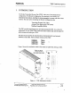
NOKIA TBU Unit Description 4.2. Dimensions and Weight Table 7. Dimensions and Weight 262 mm (10.3 in) Height 287.5 +47.5mm (1.910) heat sink maximum & kg (13.2 LB) 43. RF Performance Values Table 8. Typical RF Performance Values TX Frequency Range Gain Output Power 1805 1880 MHz 66dB 1930 1980 MHz 6.608 Version 65 W 4.4. Handling and Storage Requirements Some components inside of the TBU unit contain beryllium oxide (Bethinks must be considered when handling the TBU unit.
FCC ID: L7TKTBUL-0 € FT This Section has been removed and placed in the Confidential Section accompanying this report.
FCC ID: L7KTBUL-01 Ler This Section has been removed and placed in the Confidential Section accompanying this report.