
User's Manual

Access P oint Hardw are Installation Base Control Unit Installation
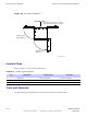
Procedure 4 -4 Installing the BCU Plinth on Concrete (Continued)
3
Set aside the plinth and drill holes where hole locations are marked.
4
Ensure that isolation pad is affixed to bottom
of each bracket. Set plinth over holes.
Secure plinth to floor using one flat isolation washer and
one Hilti—Bolt (HSL-3M 8/20) each. T orque bolts to 65 ft-lbs (8.8 N-m)
See Figure 4-7 .
5
V erify that plinth is secured to floor .
6
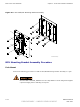
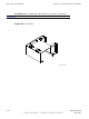
If left and right brackets have not been previously attached to B CU underside,
secure brackets to underside of B CU using four bolts, nuts, and washers each.
T orque bolts to 10 ft-lbs (13.6 N-m). See Figure 4-8
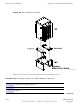
7
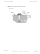
If B CU already has left and right brackets attached to its underside, set the
B CU onto the plinth and secure in place using eight screws. T orque the
screws to 10 ft-lbs (13.6 N-m). See Figure 4-8
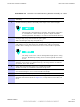
The B CU can only be set on the plinth in one direction. The
Customer Interface Compartment seats over the notched end of
the plinth.
68P09277A59 -8 4 -15
PRELIMINARY - UNDER DEVELOPMENT MA Y 2007