
User's Manual

Base Control Unit Installation Chapter 4: Access P oint Hardw are Installation
Wall Mount
P erform the following procedure to install the P ole/W all Mounting Bracket Assembly on a wall.
Procedure 4 -2 Procedure to Install Mounting Br ack et Assembly on a W all
1
Determine the height at which the Base Control Unit (B CU) will be mounted.
Make sure the wall is capable of supporting the weight, check with Site
Manager .
2
Use the W all Mounting Bracket as a template to layout the nine hole locations.
3
Drill starter holes for the anchor bolts at the locations marked.
4
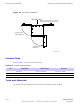
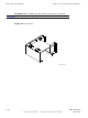
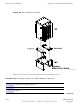
Secure W all Mounting Bracket to wall using nine
M6 bolts and washers. Refer to Figure 4-5 .
T orque bolts to 30 in-lbs (3.4 N-m).
5
Mount B CU onto W all Mounting Bracket and secure in place.
Installing the BCU
F ollow the steps in Procedure 4 -3 to install the Base Control Unit (B CU).
Procedure 4 -3 Procedure to Install the P ole Mount BCU
1
P erform the procedure for attaching the P ole Mounting Bracket Assembly described in
Procedure 4-1 .
2
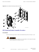
Mount the B CU onto the mounting bracket and secure using 12 screws. Refer to Figure 4-5 ).
It is recommended that a minimum of two people attach the B CU on the pole
mounting bracket.
3
B CU is ready for cabling. Proceed to Procedure 4-6 .
P erform Procedure 4 -4 to floor mount the B CU on a concrete pad.
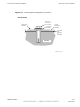
Procedure 4 -4 Installing the BCU Plinth on Concrete
1
P osition the plinth in the desired position.
2
Mark the hole locations on the floor using the plinth as a template.
Continued
4 -14 68P09277A59 -8
PRELIMINARY - UNDER DEVELOPMENT MA Y 2007