
User's Manual

Access P oint Hardw are Installation Base Control Unit Installation
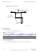
Procedure 4 -1 Procedure to Install Mounting Br ack et Assembly on a P ole
1
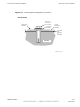
Slide non–buckle end of strap through openings in P ole Mounting Bracket
Assembly .
2
Set P ole Mounting Bracket Assembly with straps at the desired height.
Initial height is determined by customer . The bottom of the B CU
is a minimum of 1 meter from the ground. Adjust P ole/W all
Mounting Bracket Assembly to account for this minimum distance.
3
W rap strap around the pole, slide non–buckle end
through strap loop and around the pole again.
Slide end through strap loop and pull snug.
4
A ttach Bucklestrap Cutting T ool (slide strap through openings in tool,
pull gripper lever to slide strap into spindle head), slide tool towards
buckle. Place cutting tool end of tool as close to the buckle as possible.
The strap can be cut to a more manageable length prior to using
the tool. Bucklestrap Cutting T ool is a ratchet spindle and cutter
in one.
5
Turn spindle clockwise until strap is tight.
Bend the excess strap over tightened strap, cut strap, fold the cut tab into
the buckle, then close buckle.
6
Using the tool bend the strap over towards the buckle.
Remove tool and use a hammer to bend the strap more.
7
Use the hammer to bend buckle tabs over strap.
Use electrical tape to cover over the buckle and straps.
8
P erform step 3 through step 8 , for the remaining straps.
9
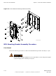
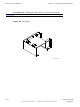
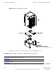
If not already attached to B CU , attach Mounting Bracket to B CU using nine
M6 bolts and washers (Refer to Figure 4-5 ). T orque bolts to 30 in–lbs (3.4
N–m).
68P09277A59 -8 4 -13
PRELIMINARY - UNDER DEVELOPMENT MA Y 2007