
User's Manual

Access P oint Hardw are Installation AC or DC P ower Cabling Installation
This equipment is designed to permit the connection of the earthed conductor of the
DC supply circuit to the earthing conductor at the equipment. If this connection is
made, all of the following conditions must be met:
• This equipment shall be connected to directly to the DC supply system earthing
electrode conductor or to a bonding jumper from an earthing terminal bar or bus
to which the DC supply system earthing electrode conductor is connected.
• This equipment shall be located in the same immediate area (such as, adjacent
cabinets) as an y other equipment that has a connection between the earthed
conductor of the same d.c. supply circuit and the earthing conductor , and also
the point of earthing of the DC system. The DC system shall not be earthed
elsewhere.
• The DC supply source is to be located within the same premises as the equipment.
• S witching or disconnecting devices shall not be in the earthed circuit conductor
between the d.c. source and the point of connection of the earthing.
F or supply connections, use wires suitable for at least 75°C .
Floating Supply voltage should not exceed 60 VDC for DC powered equipment.
Unit is intended for installation in Restricted Access Locations
Branch Circuit protection to be provided during installation. A single pole 50A rated circuit
breaker or adequately rated fuse shall be used for nominal -48 VDC installations. A Single
pole 80A rated circuit breaker or adequately rated fuse shall be used for nominal +27 VDC
installations.
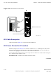
Procedure 4 -7 Procedure to Install AC P ower Cable
1
Ensure that AC power at the source is disabled before handling cable.
AC power cables are supplied by the customer and should already
have been laid out at the site.
2
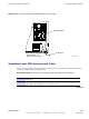
If not already done, route AC power cables through conduit to B CU Customer
Interface compartment.
3
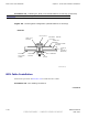
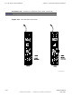
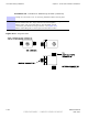
In the B CU Customer Interface compartment, open the AC Surge Module
cover by loosening two captive screws. AC Surge Module cover is hinged.
4
Loosen screws on AC power terminal block. Insert AC power cables into
GROUND , LINE and NEUTRAL and tighten screws. See Figure 4-10
Ensure a good connection.
5
Close AC Surge Module cover and secure by tightening two captive screws.
6
If required, enable AC power at the source.
68P09277A59 -8 4 -23
PRELIMINARY - UNDER DEVELOPMENT MA Y 2007