
User's Manual

Access P oint Hardw are Installation Base Control Unit Installation
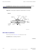
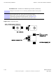
Procedure 4 -6 BCU Cabling Procedures (Continued)
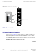
The cable access holes are covered. Remove the wing nuts and
covers before routing cables to and from the B CU Customer
Interface Compartment.
1
F or B CU Ground cable installation, B CU ground is located on the side just
behind the Customer Interface compartment door hinge. A ttach the 2–hole
lug and cable to the ground location on the B CU . A ttach other end of ground
cable to system ground bus bar .
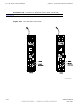
2
Ensure the AC (or DC) power is disabled at the source
before attempting to install the AC (or DC) power cabling.
F or AC power cable installation, perform Procedure 4-7 .
F or DC power cable installation, perform Procedure 4-8
3
F or RF Head DC power cable installation, perform Procedure 4-14 .
4
F or Fiber Optic cable installation, perform Procedure 4-16
5
F or RGPS cable installation, perform Procedure B -1 .
F or Local GPS cable installation, perform Procedure 4-10
6
F or Customer Input and Output cable installation, perform Procedure 4-12 .
T o avoid confusion tag the output cables.
7
F or Ethernet cable installation (if available), perform Procedure 4-11
68P09277A59 -8 4 -21
PRELIMINARY - UNDER DEVELOPMENT MA Y 2007