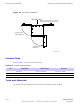
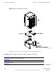
Base Control Unit Installation Figure 4-4 Chapter 4: Access Point Hardware Installation BCU Door Clearances 305 mm / 457 mm (12 in.) / (18 in.) Recommended for Fiber Connection 406 mm (16 in.) Left & Right Door 432 mm (17 in.) DACS Door ti-cdma-05732.eps Conduit Sizes Refer to Table 4-1 for the proper conduit sizes. Table 4-1 Conduit Types and Sizes No. Designation Required Size Hole Size 1 Ethernet 1 inch (25.4 mm) 1 inch (25.4 mm) 2 Power 1–1/4 inch (31.75 mm) 1–1/4 inch (31.
Access Point Hardware Installation Base Control Unit Installation • Bucklestrap Cutting Tool (Motorola P/N 6604809N01) for pole mounting bracket assembly • Safety Glasses • 13/16 Breakaway Torque Wrench 38 in-lb (4.
Base Control Unit Installation Chapter 4: Access Point Hardware Installation Figure 4-5 BCU Wall/Pole Mounting Bracket Assembly ti-cdma-04176.eps BCU Mounting Bracket Assembly Procedure Pole Mount Perform the following procedure to install the Pole/Wall Mounting Bracket Assembly on a pole. Once the BCU is installed, DO NOT use it as a step ladder. It is not designed to support a person hanging from or standing on top of it.
Access Point Hardware Installation Procedure 4-1 Base Control Unit Installation Procedure to Install Mounting Bracket Assembly on a Pole 1 Slide non–buckle end of strap through openings in Pole Mounting Bracket Assembly. 2 Set Pole Mounting Bracket Assembly with straps at the desired height. Initial height is determined by customer. The bottom of the BCU is a minimum of 1 meter from the ground. Adjust Pole/Wall Mounting Bracket Assembly to account for this minimum distance.
Base Control Unit Installation Chapter 4: Access Point Hardware Installation Wall Mount Perform the following procedure to install the Pole/Wall Mounting Bracket Assembly on a wall. Procedure 4-2 Procedure to Install Mounting Bracket Assembly on a Wall 1 Determine the height at which the Base Control Unit (BCU) will be mounted. Make sure the wall is capable of supporting the weight, check with Site Manager. 2 Use the Wall Mounting Bracket as a template to layout the nine hole locations.
Access Point Hardware Installation Base Control Unit Installation Procedure 4-4 Installing the BCU Plinth on Concrete (Continued) 3 Set aside the plinth and drill holes where hole locations are marked. 4 Ensure that isolation pad is affixed to bottom of each bracket. Set plinth over holes. Secure plinth to floor using one flat isolation washer and one Hilti—Bolt (HSL-3M 8/20) each. Torque bolts to 65 ft-lbs (8.8 N-m) See Figure 4-7 . 5 Verify that plinth is secured to floor.
Base Control Unit Installation Chapter 4: Access Point Hardware Installation Procedure 4-4 Installing the BCU Plinth on Concrete (Continued) 8 BCU is ready for cabling. Proceed to Procedure 4-6 Figure 4-6 BCU Plinth ti-cdma-04175.
Access Point Hardware Installation Base Control Unit Installation Figure 4-7 Mounting Bolt Conguration (Concrete) CONCRETE PAD HILTI-BOLT HSL-3M 8/20 LARGE FLAT WASHER OPTIONAL ISOLATION WASHER PLINTH MOUNTING BRACKET ISOLATION PAD (AFFIXED TO BRACKET) CONCRETE ti-cdma-05742.
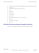
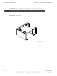
Base Control Unit Installation Figure 4-8 Chapter 4: Access Point Hardware Installation BCU Attachment to Plinth BCU Right Bracket Left Bracket Plinth Isolation Pads (Affixed to bottom of bracket s) ti-cdma-05744.eps Perform Procedure 4-5 to floor mount the BCU on a raised platform or roof.
Access Point Hardware Installation Procedure 4-5 Base Control Unit Installation Installing the Plinth on a Raised Platform or Roof Top (Continued) 4 Set aside the plinth, and drill holes where hole locations are marked. 5 Set plinth over holes. Secure plinth to platform or roof top using one large flat washer, lock washer, small flat washer, 12M nut, and 12M bolt each. Torque bolts to 65 ft-lbs (88 N-m) See Figure 4-9. If left and right brackets have not been attached to BCU, proceed to step 6.
Base Control Unit Installation Chapter 4: Access Point Hardware Installation Procedure 4-5 8 Installing the Plinth on a Raised Platform or Roof Top (Continued) BCU is ready for cabling.
Access Point Hardware Installation Base Control Unit Installation Procedure 4-6 BCU Cabling Procedures (Continued) The cable access holes are covered. Remove the wing nuts and covers before routing cables to and from the BCU Customer Interface Compartment. 1 For BCU Ground cable installation, BCU ground is located on the side just behind the Customer Interface compartment door hinge. Attach the 2–hole lug and cable to the ground location on the BCU.
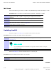
AC or DC Power Cabling Installation Chapter 4: Access Point Hardware Installation AC or DC Power Cabling Installation ■ ■ ■ ■ ■ ■ ■ ■ ■ ■ ■ ■ ■ ■ ■ ■ ■ ■ ■ ■ ■ ■ ■ ■ ■ ■ ■ ■ ■ ■ ■ ■ ■ ■ ■ ■ ■ ■ ■ ■ ■ ■ ■ ■ ■ ■ ■ ■ ■ ■ ■ ■ ■ ■ ■ ■ ■ ■ ■ ■ ■ ■ ■ ■ Objective This section contains the procedure for installing the AC power cable. This equipment uses dangerous voltages and is capable of causing death.
Access Point Hardware Installation AC or DC Power Cabling Installation This equipment is designed to permit the connection of the earthed conductor of the DC supply circuit to the earthing conductor at the equipment.
AC or DC Power Cabling Installation Chapter 4: Access Point Hardware Installation Figure 4-10 BCU AC Power Connection Neutral Connection Ground Connection Line Connection ti-cdma-04182.eps DC Cable Description Cable M as listed inTable 3-1 is required for this installation. DC Power Connection Procedure Follow the steps in Procedure 4-8 to connect a nominal +27 or —48 VDC power cable to the Base Control Unit (BCU).
Access Point Hardware Installation AC or DC Power Cabling Installation Procedure 4-8 Procedure to Install DC Power Cable (Continued) 1 Ensure that DC power at the source is disabled before handling cable. DC power cables are supplied by the customer and should already have been laid out at the site. 2 If not already done, route DC power cables through conduit to BCU Customer Interface compartment.
AC or DC Power Cabling Installation Chapter 4: Access Point Hardware Installation Procedure 4-8 Procedure to Install DC Power Cable (Continued) 6 If required, enable DC power at the source. Figure 4-11 BCU DC Power Connection Ground Ground -48 VDC Connection +27VDC Connection +27VDC -48VDC ti-cdma-05745.
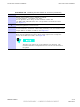
Access Point Hardware Installation Local GPS Cabling Installation Local GPS Cabling Installation ■ ■ ■ ■ ■ ■ ■ ■ ■ ■ ■ ■ ■ ■ ■ ■ ■ ■ ■ ■ ■ ■ ■ ■ ■ ■ ■ ■ ■ ■ ■ ■ ■ ■ ■ ■ ■ ■ ■ ■ ■ ■ ■ ■ ■ ■ ■ ■ ■ ■ ■ ■ ■ ■ ■ ■ ■ ■ ■ ■ ■ ■ ■ ■ Objective The objective of this procedure is to install the Local (RF) Global Positioning System (RF GPS) cabling. Tools and Materials provides the quantities and descriptions of the cables.
Local GPS Cabling Installation Chapter 4: Access Point Hardware Installation Procedure 4-9 Procedure to Install Surge Arrestor (Continued) Crimp one end each of a 6 – 8 inch long, #6 AWG cable to the lug nuts. 5 Unscrew knurled nut from surge arrestor and attach ground lug. Screw knurled nut into surge arrestor and hand tighten. Attach other end of ground cable to the threaded ground connection just above the surge arrestor. See Figure 4-13. Attach self locking nut to secure ground connection to BCU.
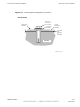
Access Point Hardware Installation Local GPS Cabling Installation Figure 4-13 Surge Arrestor Orientation and Ground Location RF -GPS Cable To Antenna Ground Cable (Optional Connection) ti-cdma-05831.eps Installing Local GPS Antenna and Cable Figure 4-14 shows the components of the Local GPS. The Local GPS is connected to the BCU via the Customer Interface compartment.
Local GPS Cabling Installation Chapter 4: Access Point Hardware Installation Procedure 4-10 Procedure for Installing Local GPS Antenna and Cabling (Continued) 3 The roof structure on which the mounting pole is attached should be veried by a qualied structural engineer for the weight of the Local GPS engine and mounting hardware or under adverse conditions for the installation area Mounting the Local GPS antenna and hardware to an inadequate roof surface and/or using inadequate installation methods can
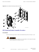
Access Point Hardware Installation Local GPS Cabling Installation Procedure 4-10 Procedure for Installing Local GPS Antenna and Cabling (Continued) Figure 4-14 Local GPS Installation and Components Diagram NOTE: 1. TOTAL WEIGHT FOR GPS ANTENNA ASSEMBLY -- 0.65 LBS ANTENNA (GCNTM20A3A) (SEE NOTE 1) N CONNECTOR ANTENNA IS DESIGNED FOR A 1--IN DIA. NOMINAL PIPE. RUBBER PAD (P/O ANTENNA) THE ANTENNA CAN BE INSTALLED ON A 3/4--IN DIA.
Ethernet Cabling Installation Chapter 4: Access Point Hardware Installation Ethernet Cabling Installation ■ ■ ■ ■ ■ ■ ■ ■ ■ ■ ■ ■ ■ ■ ■ ■ ■ ■ ■ ■ ■ ■ ■ ■ ■ ■ ■ ■ ■ ■ ■ ■ ■ ■ ■ ■ ■ ■ ■ ■ ■ ■ ■ ■ ■ ■ ■ ■ ■ ■ ■ ■ ■ ■ ■ ■ ■ ■ ■ ■ ■ ■ ■ ■ Objective This section contains the procedure for installing the Ethernet cables. Cable Description Cable J as listed in Table 3-1 is required for installation.
Access Point Hardware Installation Customer Input/Output Cabling Installation Customer Input/Output Cabling Installation ■ ■ ■ ■ ■ ■ ■ ■ ■ ■ ■ ■ ■ ■ ■ ■ ■ ■ ■ ■ ■ ■ ■ ■ ■ ■ ■ ■ ■ ■ ■ ■ ■ ■ ■ ■ ■ ■ ■ ■ ■ ■ ■ ■ ■ ■ ■ ■ ■ ■ ■ ■ ■ ■ ■ ■ ■ ■ ■ ■ ■ ■ ■ ■ Objective This section contains the procedures for installing the Customer Defined Input/Output cables. Cable Descriptions Cable F as listed inTable 3-1 is required for installation.