
User's Manual

Access P oint Hardw are Installation Base Control Unit Installation
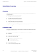
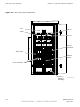
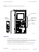
Figure 4 -2 BCU P ower and Customer Interface Compartment
ti-cdma-04174.eps
Ethernet
connection
s
RGPS connector
behind cover
AC Power
compartment
with cover removed
Customer Input /
Output connectors
RF -GPS Module
Electrical
The B CU is designed to use 100–240 V AC , +27 VDC , or –48 VDC .
If powered by single phase AC voltage (customer supplied), the range is 100/240 V AC @ 50/60
Hz, 16A max., +20 to +30 VDC , 78A max., or -60 to -30 VDC , 38A max.. The AC voltage is
converted to +54 VDC within the P ower Supply Modules (PSM).
If powered by +27 VDC (customer supplied) the range is +21 to +30 VDC . See Figure 4 -11
If powered by —48 VDC (customer supplied) the range is –60 to –40 VDC . See Figure 4 -11
68P09277A59 -8 4 -7
PRELIMINARY - UNDER DEVELOPMENT MA Y 2007