
User's Manual

Div ersit y Access P oint (DAP) RF Head Assembly Installation Chapter 4: Access P oint Hardw are Installation
Procedure 4 -13 Procedure to Install RF Head Assembly (Continued)
10
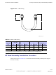
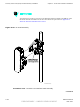
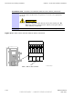
Slide the RF Head into the side mounting bracket and retention bracket
slots. See Figure A-3
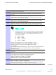
1 1
Ensure that the RF Head is properly mounted and its movement
is not obstructed. T o adjust the tilt (up/down angle) loosen two
M6 screws on each side of unit using a 10 mm socket or crescent
wrench. R ange of motion is 25 degrees from horizontal. The
retention bracket serves as an indicator of the tilt in degrees.
When RF Head is set at the desired position, tighten captive
bolts on retention bracket. T orque bolts to 45 in-lbs (5.0 N-m).
Tighten captive screws at pivot on each side of unit to
secure RF Head. T orque screws to 45 in-lbs (5.0 N-m).
12
Proceed to Procedure 4-14 for RF Head DC P ower Cable connection
procedure.
4 -40 68P09277A59 -8
PRELIMINARY - UNDER DEVELOPMENT MA Y 2007