
User's Manual


RGPS Cabling Installation Appendix B: Alternate RGPS Installation
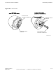
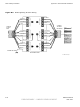
Figure B -3 Installing the R emote GPS Head
ti-cdma-05740.eps
WALL MOUNTING
BRACKETS (2)
CLAMP BRACKETS (2)
U-BOLTS
CABLE TO LIGHTNING
ARRESTOR (CABLE C)
RGPS HEAD WITH
12 PIN MALE
CONNECTOR
MATING
CONNECTORS
RGPS INTERFACE
CABLE WITH 12 PIN
FEMALE CONNECTOR
ON ONE END AND
UNTERMINATED WIRE
ON OTHER END
CABLE TO LIGHTNING
ARRESTOR (CABLE C)
ALTERNATE RGPS HEAD (MOTOR OLA
P/N 0186012H04)
RGPS H EAD (MOTORO LA
P/N STLN6594)
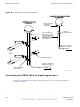
Connecting the RGPS Cable to Lightning Arrestor
Figure B -4 is a diagram of the RGPS connections. Figure B -5 is a detail of the Lightning
Arrestor connections.
B -6 68P09277A59 -8
PRELIMINARY - UNDER DEVELOPMENT MA Y 2007