
User's Manual

RGPS Cabling Installation Appendix B: Alternate RGPS Installation
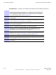
Procedure B -1 Procedure for Installing the RGPS Head and Cabling (Continued)
Mounting the RGPS head and hardware to an inadequate wall structure and/or
using inadequate installment methods can result in serious personal injury .
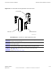
Use the appropriate mounting bolts for the mounting surface and install the
two wall mounting brackets. Refer to Figure B -3 .
3
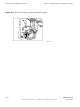
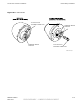
Route the 12-pin Deutsch connector of the RGPS cable (C) through the RGPS
mounting pipe.
4
Connect the RGPS cable (C) connector to the RGPS head 12-pin connector
as shown in Figure B -3 and Figure B -4 . Tighten the spinning flange on the
connector a quarter turn to secure the connection.
5
Insert the RGPS mounting pipe into the threaded mount of the RGPS head
and carefully hand-tighten.
6
Install the RGPS mounting pipe into the mounting brackets as shown in
Figure B -3 . Tighten the U -bolt clamps to secure the assembly .
7
Route the free ends of the BTS RGPS cable (L) and RGPS cable (C) to
the lightning arrestor . Remove any excess cable length and strip off
approximately 15 cm of the cables outer insulation.
8
Connect the 12 individual connectors and cable drain of each cable end to the
lightning arrestor as shown in Figure B -5 . Double check the lightning arrestor
connections for compliance with those presented in Figure B -5 .
9
Route the RGPS cable from the lightning arrestor to the bottom of the B CU .
10
If not already open, open the Customer Interface compartment.
If not already done, remove access hole cover .
1 1
Route the RGPS cable up through the access hole and connect to RGPS
D -Connector .
B -4 68P09277A59 -8
PRELIMINARY - UNDER DEVELOPMENT MA Y 2007