
User's Manual

Access P oint Hardw are Installation RGPS Cabling Installation
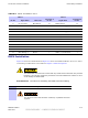
Table B -1 Pinout for Cables C and L
Cable C Cable L
Pin No.
Signal Name W ire Color
Connector A
Pin No.
Signal Name
Connector B
Pin No.
9
DC Ground 1 Blue–Black
15 RGPS Return 15
1 P ower 1
Blue
8
RGPS +54V Supply
8
8
DC Ground 2 Y ellow–Black
14 RGPS Return 14
10 P ower 2
Y ellow
7
RGPS +54V Supply
7
4
Transmit P ort (–) Green–Black
9
DA T A (-) From Head
12
5
Transmit P ort (+)
Green 1
DA T A (+) From Head
4
2
Receive P ort (–) White–Black
12
DA T A (-) T o Head
9
3
Receive P ort (+) White
4
DA T A (+) T o Head
1
7
No Connect
Red–Black
No Connect No Connect No Connect
6 No Connect
Red
No Connect No Connect No Connect
12
PPS Timing (–) Brown–Black
10
SYNC (-) From Head
10
11
PPS Timing (+)
Brown
2
SYNC (+) From Head
2
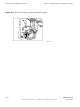
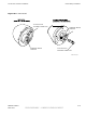
RGPS Installation
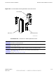
Figure B -2 shows the RGPS Head and Figure B -3 shows the RGPS installation. Be sure to factor
in mounting considerations as described in Chapter 3 Cable Descriptions .
The RGPS head must not mak e contact with an y metal surface other than the pro vided
hardw are. Use only the equipment pro vided to mount the RGPS head. F ailure to do so
could damage the RGPS head.
Procedure B -1 Procedure for Installing the RGPS Head and Cabling
1
Determine the RGPS mounting location.
2
The structure of the w all should be v eried b y a qualied structur al
engineer .
68P09277A59 -8 B -3
MA Y 2007 PRELIMINARY - UNDER DEVELOPMENT