
User's Manual

Manual RF Head Installation Procedures Appendix A: Alternate RF Head Installation Procedure
Procedure A -2 Procedure to Prepare and Install RF Head (Continued)
Install RF Head
16
Prepare the RF Head for hoisting.
A ttach carabiner to handle of RF Head.
Use the block and tackle to hoist the RF
Head to the Main Support Bracket Assembly .
Carefully hoist RF Head up to Main Support Bracket Assembly .
17
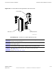
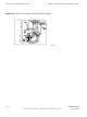
Align to captive screws on side support bracket with the Main Support
Bracket Assembly curved slots and drop into place. (Retention
brackets on each side of the Main Support Bracket Assembly
should automatically slide upward to help hold the RF Head.)
If not, slide retention bracket on Main Support Bracket Assembly up,
aligning the RF Head screw with captive nuts on the side support
brackets. Hand tighten captive screws. Do not fully tighten screws.
Refer to Figure A-3 .
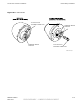
18
Ensure that the RF Head is properly
mounted and its movement is not obstructed.
Adjust the azimuth (up/down angle) loosen two M6 screws on
each side of unit (if required, use a 10 mm socket or crescent
wrench). R ange of motion is 25 degrees from horizontal.
The retention bracket serves as an indicator of the azimuth in degrees.
When RF Head is set at the desired position, tighten captive
screws on retention bracket. T orque bolts to 45 in-lbs (5.0 N-m).
Tighten captive screws at pivot of each side of unit to secure RF Head.
T orque bolts to 45 in-lbs (5.0N-m).
19
Use a 10 mm socket wrench to loosen ground lug captive screws on RF Head.
Remove ground lug.
Slide a 6 A WG wire into the ground lug.
Crimp ground lug onto wire.
V erify that 6 A WG wire is secure within ground lug.
20
Reattach ground lug onto RF Head.
Use a 10 mm socket wrench to tighten captive
screws. T orque screws to 45 in-lbs (5.0 N-m).
Secure opposite other end of ground wire to tower ground.
21
Connect DC power cables to the RF Heads.
Route DC power cables through conduit to bottom of the
B CU and up into the B CU Customer Interface Compartment.
Connect the cables to their respective RFU 1 — RFU 4 connectors by
matching the tie-wrap color with the connector color .
22
Route Fiber Optic cables down the tower to the under side of the B CU .
Connect cable to the appropriate FIBER feedthrough connector .
A -8 68P09277A59 -8
PRELIMINARY - UNDER DEVELOPMENT MA Y 2007