
User's Manual

Manual RF Head Installation Procedures Appendix A: Alternate RF Head Installation Procedure
Procedure A -1 Procedure to Install RF Head Main Support Br ack et Assembly
1
Remove nuts and washers from both ends of the U -bolt.
2
Set Main Support Bracket Assembly at the required location on the pole.
It is recommended that two people perform mounting the bracket
to the pole. One person can perform the bracket mounting by
using a block and tackle to hold bracket at the desired mounting
location.
3
Slide first U -bolt around pole and through top slots of Main
Support Bracket Assembly . Slide washers over threads.
Thread nuts on U -bolt and hand tighten.
4
Slide second U -bolt around pole and through bottom slots of
Main Support Bracket Assembly . Slide washers over threads.
Thread nuts on U -bolt and hand tighten.
5
Align Main Support Bracket Assembly on pole facing the appropriate
direction and tighten nuts using a socket wrench or power driver . T orque
nuts to 24 ft-lbs (32.5 N-m).
Installing the RF Head
F ollow the steps in Procedure A -2 to install the RF Head.
Procedure A -2 Procedure to Prepare and Install RF Head
Prepare RF Head
1
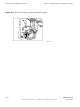
Place the RF Head on a flat surface, large finned-side down.
2
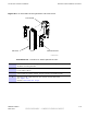
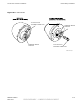
A ttach the left and right side mounting brackets
to RF Head using a T30 T orx screw driver .
The brackets straight edges face away from Main Support Bracket Assembly .
See Figure A-3
3
A ttach solar shield to side brackets by snapping the tabs on the bottom of the
shield into side bracket slots. Refer to Figure A-3 .
4
Lift shield and drop over the top of the RF Head.
Handle of RF Head slips through slot in solar shield.
The captive screws on the mounting bracket are used to secure the solar
shield to it. Tighten the captive screws to secure the solar shield to the
mounting brackets. T orque captive screws to 45 in-lbs (5.0 N-m)
5
Set the RF Head so that it is resting on the side brackets support arms and
RF Head bottom (filter if attached).
A -6 68P09277A59 -8
PRELIMINARY - UNDER DEVELOPMENT MA Y 2007