
User's Manual

Div ersit y Access P oint (DAP) RF Head Assembly Installation Chapter 4: Access P oint Hardw are Installation
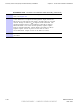
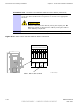
Table 4 -2 Conduit R equirements
No. Designation
Required Size
1
P ower
1–1/4 inch
2
Fiber Optic
None
Tools and Materials
• Mounting Bracket Assembly
• U -bolts
• Set of metric sockets (3/8–in or 1/4–in drivers)
• Set of standard sockets (3/8–in or 1/4–in drivers)
• Socket 3/8–in or 1/4–in driver
• T orque Driver
• Cordless P ower Driver
• Ground Lug
• Crimp T ool
• T30 T orx Screw Driver
• Adjustable Crescent W rench
• Tie -wraps of varying lengths
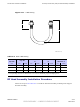
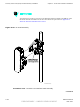
U -Bolt Specications
The U -bolt is
supplied by the Customer
. Reference Figure 4 -17 and to determine the proper
U -bolt to use. P ole mounting bracket is designed to use 3/8–inch hardware.
4 -36 68P09277A59 -8
PRELIMINARY - UNDER DEVELOPMENT MA Y 2007