
User's Manual

Manual RF Head Installation Procedures Appendix A: Alternate RF Head Installation Procedure
Manual RF Head Installation Procedures
■ ■ ■ ■ ■ ■ ■ ■ ■ ■ ■ ■ ■ ■ ■ ■ ■ ■ ■ ■ ■ ■ ■ ■ ■ ■ ■ ■ ■ ■ ■ ■ ■ ■ ■ ■ ■ ■ ■ ■ ■ ■ ■ ■ ■ ■ ■ ■ ■ ■ ■ ■ ■ ■ ■ ■ ■ ■ ■ ■ ■ ■
■
■
Overview
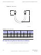
This section contains the procedures for installing the Diversity Access P oint RF Head which is
comprised of the TRX Module and antenna radome. Refer to Figure 1–2.
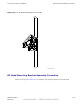
DAP RF Head
Refer to Figure 1 -4 for the major components of the DAP RF Head.
Electrical Requirements
The RF Head is designed to use 40 to 59 VDC (nominal +54 VDC) supplied through the Base
Control Unit (B CU).
Dimensions and Weight
• Dimension: 228.6 mm (9 in) W x 712 mm (28 in) H x 406 mm (16 in) D
• W eight: 27.2 kg (60 lbs)
The dimension measurements do not include connectors, hinges, handles, or latches.
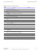
Conduit Sizes
Refer to T able A -1 for conduit sizes.
Table A -1 Conduit R equirements
No. Designation
Required Size
1
P ower
1–1/4 inch
2
Fiber Optic
None
A -2 68P09277A59 -8
PRELIMINARY - UNDER DEVELOPMENT MA Y 2007