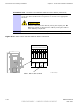
Customer Input/Output Cabling Installation Chapter 4: Access Point Hardware Installation Procedure 4-12 Procedure to Install the Customer Dened Input/Output Cables 1 If not already open, open the Customer Interface Compartment. If not already done, remove conduit plug from access hole. 2 Route the Customer Defined Input (CDI) Cable 1–2 through conduit to the underside of the BCU, through the access hole, and up to the connector labeled CUST. INPUT 1–2 3 Perform step 2 for CDI Cable 3–4.
Access Point Hardware Installation Diversity Access Point (DAP) RF Head Assembly Installation Diversity Access Point (DAP) RF Head Assembly Installation ■ ■ ■ ■ ■ ■ ■ ■ ■ ■ ■ ■ ■ ■ ■ ■ ■ ■ ■ ■ ■ ■ ■ ■ ■ ■ ■ ■ ■ ■ ■ ■ ■ ■ ■ ■ ■ ■ ■ ■ ■ ■ ■ ■ ■ ■ ■ ■ ■ ■ ■ ■ ■ ■ ■ ■ ■ ■ ■ ■ ■ ■ ■ ■ Overview This section contains the procedures for installing the Diversity Access Point RF Head Assembly which is comprised of the RF Head and antenna radome.
Diversity Access Point (DAP) RF Head Assembly Installation Table 4-2 Chapter 4: Access Point Hardware Installation Conduit Requirements No.
Access Point Hardware Installation Figure 4-17 Diversity Access Point (DAP) RF Head Assembly Installation U-Bolt Sizing C B ti-cdma-05727.eps Table 4-3 DAP U-Bolt Sizing Nominal Pipe Size Pipe OD Minimum Dimension B Maximum Dimension B Minimum Dimension C (in) (in) (mm) (in) (mm) (in) (mm) (in) (mm) 2 2.375 60.33 3.886 98.70 4.886 124.10 0.6 15 2.5 2.875 73.03 4.429 112.50 5.429 137.90 0.6 15 3 3.500 88.90 5.098 129.50 6.098 154.90 0.
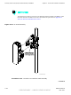
Diversity Access Point (DAP) RF Head Assembly Installation Chapter 4: Access Point Hardware Installation The following procedure is based on the RF Head arriving already assembled. If the RF head must be assembled at the site then follow the procedure in Appendix A Alternate RF Head Installation Procedure. Figure 4-18 RF Head Assembly Adjust Ret en tion Brackets slot s upward to align with side moun ting bracket slot s ti-cdma-05725.
Access Point Hardware Installation Diversity Access Point (DAP) RF Head Assembly Installation 1 From RF Head Main Support Bracket Assembly, remove nuts and washers from both ends of the U-bolts. 2 Set RF Head Main Support Bracket Assembly at the desired location on the pole. 3 Slide first U-bolt around pole and through top slots of RF Head Main Support Bracket Assembly. Slide washers over threaded ends of U-bolt. Thread nuts on U-bolt and hand tighten.
Diversity Access Point (DAP) RF Head Assembly Installation Chapter 4: Access Point Hardware Installation Procedure 4-13 Procedure to Install RF Head Assembly (Continued) 10 Slide the RF Head into the side mounting bracket and retention bracket slots. See Figure A-3 11 Ensure that the RF Head is properly mounted and its movement is not obstructed. To adjust the tilt (up/down angle) loosen two M6 screws on each side of unit using a 10 mm socket or crescent wrench.
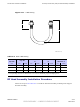
Access Point Hardware Installation RF Head DC Power Cabling Installation RF Head DC Power Cabling Installation ■ ■ ■ ■ ■ ■ ■ ■ ■ ■ ■ ■ ■ ■ ■ ■ ■ ■ ■ ■ ■ ■ ■ ■ ■ ■ ■ ■ ■ ■ ■ ■ ■ ■ ■ ■ ■ ■ ■ ■ ■ ■ ■ ■ ■ ■ ■ ■ ■ ■ ■ ■ ■ ■ ■ ■ ■ ■ ■ ■ ■ ■ ■ ■ Objective This section contains the procedure for installing the RF Head DC power cables.
RF Head DC Power Cabling Installation Chapter 4: Access Point Hardware Installation Procedure 4-14 Procedure to Install RF Head DC Power Cables (Continued) 3 Route the DC Power cables through conduit up to the tower. Bundle and secure the cables (if RF Head is not present) or connect to the appropriate RF Head. Connect or disconnect the cable by turning the coupling nut. Do not try to connect or disconnect the cable by turning the cable or other attaching components.
Access Point Hardware Installation Antenna Cabling Installation Antenna Cabling Installation ■ ■ ■ ■ ■ ■ ■ ■ ■ ■ ■ ■ ■ ■ ■ ■ ■ ■ ■ ■ ■ ■ ■ ■ ■ ■ ■ ■ ■ ■ ■ ■ ■ ■ ■ ■ ■ ■ ■ ■ ■ ■ ■ ■ ■ ■ ■ ■ ■ ■ ■ ■ ■ ■ ■ ■ ■ ■ ■ ■ ■ ■ ■ ■ Objective This section contains the procedure for installing the antenna cables.
RF Head Ground Cabling Installation Chapter 4: Access Point Hardware Installation RF Head Ground Cabling Installation ■ ■ ■ ■ ■ ■ ■ ■ ■ ■ ■ ■ ■ ■ ■ ■ ■ ■ ■ ■ ■ ■ ■ ■ ■ ■ ■ ■ ■ ■ ■ ■ ■ ■ ■ ■ ■ ■ ■ ■ ■ ■ ■ ■ ■ ■ ■ ■ ■ ■ ■ ■ ■ ■ ■ ■ ■ ■ ■ ■ ■ ■ ■ ■ The RF Head comes with a ground lug attached, but no ground wire.
Access Point Hardware Installation Fiber Optic Cabling Installation Fiber Optic Cabling Installation ■ ■ ■ ■ ■ ■ ■ ■ ■ ■ ■ ■ ■ ■ ■ ■ ■ ■ ■ ■ ■ ■ ■ ■ ■ ■ ■ ■ ■ ■ ■ ■ ■ ■ ■ ■ ■ ■ ■ ■ ■ ■ ■ ■ ■ ■ ■ ■ ■ ■ ■ ■ ■ ■ ■ ■ ■ ■ ■ ■ ■ ■ ■ ■ Objective This section contains the procedure for installing the fiber optic cables. Cable Description Cable H as listed in Table 3-1 is required for installation. The minimum bend radius for this cable is 90 mm.
Fiber Optic Cabling Installation Procedure 4-16 Chapter 4: Access Point Hardware Installation Procedure to Install Fiber Optic Cables (Continued) appropriate RF Head. Twist coupling nut until it stops (detent). Use tie-wraps or appropriate clamps to secure cable to tower.
Chapter 5 Optional Equipment ■ ■ ■ ■ ■ ■ ■ ■ ■ ■ ■ ■ ■ ■ ■ ■ ■ ■ ■ ■ ■ ■ ■ ■ ■ ■ ■ ■ ■ ■ ■ ■ ■ ■ ■ ■ ■ ■ ■ ■ ■ ■ ■ ■ ■ ■ ■ ■ ■ ■ ■ ■ ■ ■ ■ ■ ■ ■ ■ ■ ■ ■ ■ ■ ■ ■ 68P09277A59-8 MAY 2007 5-1 PRELIMINARY - UNDER DEVELOPMENT
Rack Mounting Chapter 5: Optional Equipment Rack Mounting ■ ■ ■ ■ ■ ■ ■ ■ ■ ■ ■ ■ ■ ■ ■ ■ ■ ■ ■ ■ ■ ■ ■ ■ ■ ■ ■ ■ ■ ■ ■ ■ ■ ■ ■ ■ ■ ■ ■ ■ ■ ■ ■ ■ ■ ■ ■ ■ ■ ■ ■ ■ ■ ■ ■ ■ ■ ■ ■ ■ ■ ■ ■ ■ Rack Mount Instructions to be followed in all rack mount installations for all voltage range equipment (+27 VDC, -48 VDC, and A/C): 1.
Access Point Hardware Installation Optional Band Pass Filters Optional Band Pass Filters ■ ■ ■ ■ ■ ■ ■ ■ ■ ■ ■ ■ ■ ■ ■ ■ ■ ■ ■ ■ ■ ■ ■ ■ ■ ■ ■ ■ ■ ■ ■ ■ ■ ■ ■ ■ ■ ■ ■ ■ ■ ■ ■ ■ ■ ■ ■ ■ ■ ■ ■ ■ ■ ■ ■ ■ ■ ■ ■ ■ ■ ■ ■ ■ Overview This chapter contains general information and procedures for installing optional equipment. Band pass filters are available as optional equipment to accommodate customers with specific band allocations.
Optional Band Pass Filters Chapter 5: Optional Equipment Filter Requirements Weight and Dimensions The band pass filter(s) used should meet the following requirements: • Weight: 1.6 kg (3.5 lbs) • Dimensions: 50 mm (2 in) W x 150 mm (6 in) H x 100 mm (4 in) D. Figure 5-1 Band Pass Filter Filter Mounting Figure 5-2 shows the optimal mounting position on the RF Carrier Unit (RFCU). The filters are mounted such that cable lengths are kept to a minimum.
Access Point Hardware Installation Motorola Stability Oscillator (MSO) Motorola Stability Oscillator (MSO) ■ ■ ■ ■ ■ ■ ■ ■ ■ ■ ■ ■ ■ ■ ■ ■ ■ ■ ■ ■ ■ ■ ■ ■ ■ ■ ■ ■ ■ ■ ■ ■ ■ ■ ■ ■ ■ ■ ■ ■ ■ ■ ■ ■ ■ ■ ■ ■ ■ ■ ■ ■ ■ ■ ■ ■ ■ ■ ■ ■ ■ ■ ■ ■ Overview The Motorola Stability Oscillator (MSO) is available as optional equipment to accommodate customers that want this backup timing module.
Motorola Stability Oscillator (MSO) Chapter 5: Optional Equipment 5-6 68P09277A59-8 PRELIMINARY - UNDER DEVELOPMENT MAY 2007
Chapter 6 What’s Next and Cleanup ■ ■ ■ ■ ■ ■ ■ ■ ■ ■ ■ ■ ■ ■ ■ ■ ■ ■ ■ ■ ■ ■ ■ ■ ■ ■ ■ ■ ■ ■ ■ ■ ■ ■ ■ ■ ■ ■ ■ ■ ■ ■ ■ ■ ■ ■ ■ ■ ■ ■ ■ ■ ■ ■ ■ ■ ■ ■ ■ ■ ■ ■ ■ ■ ■ ■ 68P09277A59-8 MAY 2007 6-1 PRELIMINARY - UNDER DEVELOPMENT
What’s Next Chapter 6: What’s Next and Cleanup What’s Next ■ ■ ■ ■ ■ ■ ■ ■ ■ ■ ■ ■ ■ ■ ■ ■ ■ ■ ■ ■ ■ ■ ■ ■ ■ ■ ■ ■ ■ ■ ■ ■ ■ ■ ■ ■ ■ ■ ■ ■ ■ ■ ■ ■ ■ ■ ■ ■ ■ ■ ■ ■ ■ ■ ■ ■ ■ ■ ■ ■ ■ ■ ■ ■ Introduction Optimization is the next procedure you should perform. There are two things left to do before you begin the optimization: 1. Clean up the site 2.
Access Point Hardware Installation Site Cleanup Site Cleanup ■ ■ ■ ■ ■ ■ ■ ■ ■ ■ ■ ■ ■ ■ ■ ■ ■ ■ ■ ■ ■ ■ ■ ■ ■ ■ ■ ■ ■ ■ ■ ■ ■ ■ ■ ■ ■ ■ ■ ■ ■ ■ ■ ■ ■ ■ ■ ■ ■ ■ ■ ■ ■ ■ ■ ■ ■ ■ ■ ■ ■ ■ ■ ■ Tools Place all hand and power tools in the installation tool kit or other appropriate place. Note any tools that need replacement, cleaning, or adjustment. Materials Place any leftover materials in a location specified by the site manager.
Installation Completion Checklist Chapter 6: What’s Next and Cleanup Installation Completion Checklist ■ ■ ■ ■ ■ ■ ■ ■ ■ ■ ■ ■ ■ ■ ■ ■ ■ ■ ■ ■ ■ ■ ■ ■ ■ ■ ■ ■ ■ ■ ■ ■ ■ ■ ■ ■ ■ ■ ■ ■ ■ ■ ■ ■ ■ ■ ■ ■ ■ ■ ■ ■ ■ ■ ■ ■ ■ ■ ■ ■ ■ ■ ■ ■ Installation Completion Checklist Check the items listed in Table 6-1. Directions Fill out the installation completion checklist and make any necessary copies. You may copy this check sheet as needed.
Access Point Hardware Installation Installation Completion Checklist Table 6-1 Hardware Installation Checklist Item No. Item 1 Equipment is not damaged. 2 Air flow clearance requirements are met. 3 Base Control Unit (BCU) is securely mounted to wall or pole. 4 BCU and RF Carrier Unit (RFCU) are RF cabled correctly. 5 BCU and RFCU are DC power cabled correctly. 6 BCU is ethernet cabled. (If installed) 7 RF Head is securely mounted to pole.
Installation Completion Checklist Chapter 6: What’s Next and Cleanup 6-6 68P09277A59-8 PRELIMINARY - UNDER DEVELOPMENT MAY 2007
Appendix A Alternate RF Head Installation Procedure 68P09277A59-8 MAY 2007 A-1 PRELIMINARY - UNDER DEVELOPMENT
Manual RF Head Installation Procedures Appendix A: Alternate RF Head Installation Procedure Manual RF Head Installation Procedures ■ ■ ■ ■ ■ ■ ■ ■ ■ ■ ■ ■ ■ ■ ■ ■ ■ ■ ■ ■ ■ ■ ■ ■ ■ ■ ■ ■ ■ ■ ■ ■ ■ ■ ■ ■ ■ ■ ■ ■ ■ ■ ■ ■ ■ ■ ■ ■ ■ ■ ■ ■ ■ ■ ■ ■ ■ ■ ■ ■ ■ ■ ■ ■ Overview This section contains the procedures for installing the Diversity Access Point RF Head which is comprised of the TRX Module and antenna radome. Refer to Figure 1–2.
Access Point Hardware Installation Manual RF Head Installation Procedures Tools and Materials • Mounting Bracket Assembly • U-bolts • Set of metric sockets (3/8–in or 1/4–in) • Set of standard sockets (3/8–in or 1/4–in) • 3/8–in or 1/4–in driver • Torque Driver • Cordless Power Driver • Ground Lug • Crimp Tool • T30 Torx Screw Driver • Adjustable Crescent Wrench U-Bolt Specications The U-bolt is supplied by the Customer.
Manual RF Head Installation Procedures Appendix A: Alternate RF Head Installation Procedure Figure A-1 U-Bolt Sizing C B ti-cdma-05727.eps Table A-2 DAP U-Bolt Sizing Nominal Pipe Size Pipe OD Minimum Dimension B Maximum Dimension B Minimum Dimension C (in) (in) (mm) (in) (mm) (in) (mm) (in) (mm) 2 2.375 60.33 3.886 98.70 4.886 124.10 0.6 15 2.5 2.875 73.03 4.429 112.50 5.429 137.90 0.6 15 3 3.500 88.90 5.098 129.50 6.098 154.90 0.
Access Point Hardware Installation Figure A-2 Manual RF Head Installation Procedures RF Head Mounting Bracket Assembly ti-cdma-04179.eps RF Head Mounting Bracket Assembly Procedure Follow the steps in Procedure A-1 to install the pole mounting bracket for the RF Head.
Manual RF Head Installation Procedures Appendix A: Alternate RF Head Installation Procedure Procedure A-1 Procedure to Install RF Head Main Support Bracket Assembly 1 Remove nuts and washers from both ends of the U-bolt. 2 Set Main Support Bracket Assembly at the required location on the pole. It is recommended that two people perform mounting the bracket to the pole. One person can perform the bracket mounting by using a block and tackle to hold bracket at the desired mounting location.
Access Point Hardware Installation Manual RF Head Installation Procedures Procedure A-2 Procedure to Prepare and Install RF Head (Continued) 6 Install the antenna (Radome). Hook the antenna top support brackets over the bolts near the top of the RF Head. Push the bottom of the antenna and hook those brackets over the bolts near the bottom of the RF Head. 7 Secure antenna using a 10 mm socket and driver to tighten the 4 screws. Torque the bolts to 45 in-lbs (5.0 N-m).
Manual RF Head Installation Procedures Appendix A: Alternate RF Head Installation Procedure Procedure A-2 Procedure to Prepare and Install RF Head (Continued) Install RF Head 16 Prepare the RF Head for hoisting. Attach carabiner to handle of RF Head. Use the block and tackle to hoist the RF Head to the Main Support Bracket Assembly. Carefully hoist RF Head up to Main Support Bracket Assembly.
Access Point Hardware Installation Manual RF Head Installation Procedures Figure A-3 RF Head Side Mounting Brackets and Solar Shield Solar Shield RF Head 2X Side Brackets ti-cdma-04195.eps Procedure A-3 Procedure to Install Optional RF Filter 1 From Procedure A-2. If already attached to side mounting brackets, remove RF Filter mounting bracket. 2 Secure RF Filter to filter mounting bracket using four screws. Torque screws to 45 in-lbs (5 N-m).
Manual RF Head Installation Procedures Appendix A: Alternate RF Head Installation Procedure Figure A-4 Antenna to Filter RF Cable Connection Diagram DIV ti-cdma-05748.
Appendix B Alternate RGPS Installation 68P09277A59-8 MAY 2007 B-1 PRELIMINARY - UNDER DEVELOPMENT
RGPS Cabling Installation Appendix B: Alternate RGPS Installation RGPS Cabling Installation ■ ■ ■ ■ ■ ■ ■ ■ ■ ■ ■ ■ ■ ■ ■ ■ ■ ■ ■ ■ ■ ■ ■ ■ ■ ■ ■ ■ ■ ■ ■ ■ ■ ■ ■ ■ ■ ■ ■ ■ ■ ■ ■ ■ ■ ■ ■ ■ ■ ■ ■ ■ ■ ■ ■ ■ ■ ■ ■ ■ ■ ■ ■ ■ Objective This section contains procedures for installing the Remote Global Positioning System (RGPS). Cable Description Cables C and L as listed in Table 3-1 are required for installation.
Access Point Hardware Installation RGPS Cabling Installation Table B-1 Pinout for Cables C and L Cable C Pin No. Cable L Signal Name Wire Color Connector A Pin No.
RGPS Cabling Installation Appendix B: Alternate RGPS Installation Procedure B-1 Procedure for Installing the RGPS Head and Cabling (Continued) Mounting the RGPS head and hardware to an inadequate wall structure and/or using inadequate installment methods can result in serious personal injury. Use the appropriate mounting bolts for the mounting surface and install the two wall mounting brackets. Refer to Figure B-3.
Access Point Hardware Installation RGPS Cabling Installation Figure B-2 RGPS Head RGPS HEAD (MOTOROLA P/N STLN6594) ALTERN ATE RGPS HEAD (MOTOROLA P/N 0186012H04) 12-PIN DEUTSCH TYPE MMP CONNECTOR THREADED MOUNT ADAPTER THREADED MOUNT ADAPTER 12-PIN DEUTSCH TYPE MMP CONNECTOR ti-cdma-05702.
RGPS Cabling Installation Appendix B: Alternate RGPS Installation Figure B-3 Installing the Remote GPS Head ALTERN ATE RGPS HEAD (MOTOR OLA P/ N 0186012H04) RGPS H EAD (MOTORO LA P/ N STLN6594) RGPS HEAD WITH 12 PIN MALE CONNECTOR RGPS INTERFACE CABLE WITH 12 PIN FEMALE CONNECTOR ON ONE END AND UNTERMINATED WIRE ON OTHER END MATING CONNECTORS CABLE TO LIGHTNING ARRESTOR (CABLE C) U-BOLTS CLAMP BRACKETS (2) CABLE TO LIGHTNING ARRESTOR (CABLE C) WALL MOUNTING BRACKETS (2) ti-cdma-05740.
Access Point Hardware Installation RGPS Cabling Installation Figure B-4 RGPS to Base Control Unit Connection Diagram RGPS H EAD (MOTORO LA P/N STLN6594) ALTERN ATE RGPS HEAD (MOTOR OLA P/N 0186012H04) D-CONNECTOR TO BTS - OR - Re d/Black 11 Re d 3 Green /Blac k 9 Green Brown 1 12 4 10 2 Blue 8 Ye llow 7 Blue/Bl a ck 15 Ye llow/Black 14 No Connection White/Bla ck White Brown/Black C L No Connection 1 3 9 Yellow 10 2 11 8 12 Yellow Yellow/Black 7 6 4 Yellow/Black 5 CELL
RGPS Cabling Installation Appendix B: Alternate RGPS Installation Figure B-5 RGPS Lightning Arrestor Wiring Yellow/Black Yellow Green White/Black White Cable Drain Brown/Black Brown +17V DC Lines Red Blue Yellow/Black Yellow Green/Black Green White/Black White Cable Drain +17V DC Equipm ent Red/Black Blue/Black C (RGPS) TO RGPS RECEIVER +17V DC Lines Green/Black +17V DC Equipment L (RGPS) TO BCU UNIT +40V DC Lines Blue + 40V DC E quipm ent Blue/Black Red/Black Blue 1 White/Black 2 W
Appendix C MMI Cable Fabrication 68P09277A59-8 MAY 2007 C-1 PRELIMINARY - UNDER DEVELOPMENT
MMI Cable Fabrication Appendix C: MMI Cable Fabrication MMI Cable Fabrication ■ ■ ■ ■ ■ ■ ■ ■ ■ ■ ■ ■ ■ ■ ■ ■ ■ ■ ■ ■ ■ ■ ■ ■ ■ ■ ■ ■ ■ ■ ■ ■ ■ ■ ■ ■ ■ ■ ■ ■ ■ ■ ■ ■ ■ ■ ■ ■ ■ ■ ■ ■ ■ ■ ■ ■ ■ ■ ■ ■ ■ ■ ■ ■ Purpose If the Motorola SLN2006A Man Machine Interface (MMI) Interface Kit is not available, cables can be fabricated by the user to interface a nine-pin serial connector on an Line Maintenance Facility (LMF) computer platform with an MMI c
Access Point Hardware Installation MMI Cable Fabrication Figure C-1 Fabricated MMI Cable Details 8-Contact MMI Plug Socket Numbering (Mating Side) DB-9 Plug Socket Numbering (Mating Side) Item B 1 3 5 7 5 4 3 2 1 2 4 6 8 9 8 7 6 FABRICATION NOTES: 1. Separate wires at unterminated end of ribbon cable as required to connect to DB-9 connector contacts 2. Dark wire on ribbon cable of cable assembly 3009786R01 connects to pin 1 of the 8-contact plug 3.
C-2 68P09277A59-8 PRELIMINARY - UNDER DEVELOPMENT MAY 2007