
User's Manual

Customer Dened Input/Output Cables Chapter 3: Cable Descriptions
Customer Dened Input and Output Connector Pinouts
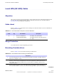
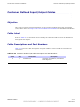
Input Pins T able 3 -11 lists the pinouts for the Customer Defined Input 1 -4 and 5–8 connectors.
Refer to Figure 4 -16 .
Table 3 -11 Customer Dened Input Connector Pins 1–4 and 5–8
Pin Number Description Pin Number Description
Connector 1–4 Connector 5–8
1
Customer Defined Input 1
1
Customer Defined Input 5
2
Customer Defined Input 1 Return
2
Customer Defined Input 5 Return
3
Customer Defined Input 2
3
Customer Defined Input 6
4
Customer Defined Input 2 Return
4
Customer Defined Input 6 Return
5
Customer Defined Input 3
5
Customer Defined Input 7
6
Customer Defined Input 3 Return
6
Customer Defined Input 7 Return
7
Customer Defined Input 4
7
Customer Defined Input 8
8
Customer Defined Input 4 Return
8
CustomerDefined Input 8 Return
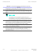
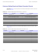
T able 3 -12 lists the pinouts for the Customer Defined Input 9 -12 and 13–16 connectors. Refer
to Figure 4 -16
Table 3 -12 Customer Dened Input Connector Pins 9–12 and 13–16
Pin Number Description Pin Number Description
Connector 9–12 Connector 13–16
1
Customer Defined Input 9
1
Customer Defined Input 13
2
Customer Defined Input 9 Return
2
Customer Defined Input 13 Return
3
Customer Defined Input 10
3
Customer Defined Input 14
4
Customer Defined Input 10 Return
4
Customer Defined Input 14 Return
5
Customer Defined Input 11
5
Customer Defined Input 15
6
Customer Defined Input 11 Return
6
Customer Defined Input 15 Return
7
Customer Defined Input 12
7
Customer Defined Input 16
8
Customer Defined Input 12 Return
8
Customer Defined Input 16 Return
3 -18 68P09277A59 -8
PRELIMINARY - UNDER DEVELOPMENT MA Y 2007