
User's Manual

Access P oint Hardw are Installation Customer Dened Input/Output Cables
Customer Dened Input/Output Cables
■ ■ ■ ■ ■ ■ ■ ■ ■ ■ ■ ■ ■ ■ ■ ■ ■ ■ ■ ■ ■ ■ ■ ■ ■ ■ ■ ■ ■ ■ ■ ■ ■ ■ ■ ■ ■ ■ ■ ■ ■ ■ ■ ■ ■ ■ ■ ■ ■ ■ ■ ■ ■ ■ ■ ■ ■ ■ ■ ■ ■ ■
■
■
Objective
This section contains general information on the Customer Defined Input (CDI) and Output
(CDO) cables. Refer to Chapter 4 Access P oint Hardware Installation for installation information.
Cable Label
Refer to T able 3 -1 for the labels used to identify the cables that will be shown in illustrations
throughout this chapter .
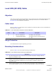
Cable Descriptions and Part Numbers
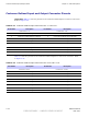
T able 3 -10 gives the cable descriptions and part numbers used to install the Customer I/O
connectors.
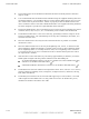
Table 3 -10 Customer Dened I/O Cable Description and P art Numbers
Cable Qty
Part Number Description
F
1 SGLN6414A
Assembly , Installation, Installation
Hdw Pkg B CU
68P09277A59 -8 3 -17
PRELIMINARY - UNDER DEVELOPMENT MA Y 2007