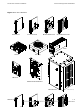
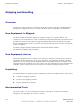
Access Point Hardware Installation Access Point Equipment Identication Figure 1-3 BCU Hardware Alarm Card Controller Card Modem Card Card Circuit Breaker Card PSU Heater Fan Tray I/O Panel Wall/Pole Mount Bracket BCU Chassis 68P09277A59-8 ti-cdma-04197.
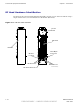
Access Point Equipment Identication Chapter 1: Introduction RF Head Hardware Identication The Diversity Access Point (DAP) RF Head Assembly consists of a two antenna element using a single radome and a (one Transmit/Receive RF Module (RF Head)). Figure 1-4 DAP RF Head Hardware Access Panel RF Head Radome Ground Location Fiber Optic Connector RF Connector RF Connector DC Power Connector ti-cdma-04168.
Chapter 2 Site Preparation ■ ■ ■ ■ ■ ■ ■ ■ ■ ■ ■ ■ ■ ■ ■ ■ ■ ■ ■ ■ ■ ■ ■ ■ ■ ■ ■ ■ ■ ■ ■ ■ ■ ■ ■ ■ ■ ■ ■ ■ ■ ■ ■ ■ ■ ■ ■ ■ ■ ■ ■ ■ ■ ■ ■ ■ ■ ■ ■ ■ ■ ■ ■ ■ ■ ■ 68P09277A59-8 MAY 2007 2-1 PRELIMINARY - UNDER DEVELOPMENT
Site Preparation Overview Chapter 2: Site Preparation Site Preparation Overview ■ ■ ■ ■ ■ ■ ■ ■ ■ ■ ■ ■ ■ ■ ■ ■ ■ ■ ■ ■ ■ ■ ■ ■ ■ ■ ■ ■ ■ ■ ■ ■ ■ ■ ■ ■ ■ ■ ■ ■ ■ ■ ■ ■ ■ ■ ■ ■ ■ ■ ■ ■ ■ ■ ■ ■ ■ ■ ■ ■ ■ ■ ■ ■ Overview This chapter provides the procedures and information to verify that the site is ready for equipment installation.
Access Point Hardware Installation Prepare Site for Equipment Arrival Prepare Site for Equipment Arrival ■ ■ ■ ■ ■ ■ ■ ■ ■ ■ ■ ■ ■ ■ ■ ■ ■ ■ ■ ■ ■ ■ ■ ■ ■ ■ ■ ■ ■ ■ ■ ■ ■ ■ ■ ■ ■ ■ ■ ■ ■ ■ ■ ■ ■ ■ ■ ■ ■ ■ ■ ■ ■ ■ ■ ■ ■ ■ ■ ■ ■ ■ ■ ■ Description This information covers various topics not all of which are needed at every site. Based on the site characteristics execute the steps that apply to your site.
Shipping and Handling Chapter 2: Site Preparation Shipping and Handling ■ ■ ■ ■ ■ ■ ■ ■ ■ ■ ■ ■ ■ ■ ■ ■ ■ ■ ■ ■ ■ ■ ■ ■ ■ ■ ■ ■ ■ ■ ■ ■ ■ ■ ■ ■ ■ ■ ■ ■ ■ ■ ■ ■ ■ ■ ■ ■ ■ ■ ■ ■ ■ ■ ■ ■ ■ ■ ■ ■ ■ ■ ■ ■ Overview The purpose of this chapter is to describe how the Base Control Unit (BCU) and RF Head are packaged for shipping and how to correctly unpack the units in preparation for installation.
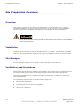
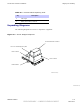
Access Point Hardware Installation Table 2-1 Shipping and Handling Recommended Unpacking Tools Description Qty 1 Tin snips 1 Knife, box cutter, scissors Unpacking Diagrams The following diagrams show how to unpack the equipment. Figure 2-1 Shrink Wrapped Shipment Pole Mount Bracket Container Boxes are shrinkwrapped to pallet DAP Container BCU Container Pallet Container ti--cdma--05734.eps ti-cdma-04922.
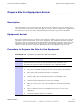
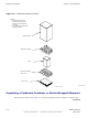
Shipping and Handling Chapter 2: Site Preparation Figure 2-2 Cardboard Shipping Container NOTE: 1. Normally this styrofoam packing is attached to the pallet. it is shown exploded for clarity 2. This example shows the BCU shipping container. Cardboard Box Styrofoam Packing BCU Styrofoam Packing (See note 1) Wood Crate ti--cdma--04169.eps ti-cdma-04922.
Access Point Hardware Installation Shipping and Handling Procedure 2-2 Unpacking Equipment from a Cardboard Container or Shrink Wrap 1 Inspect for damage. Components may or may not be delivered on one pallet. Procedure assumes components are delivered in separate containers on one pallet. 2 If container is made of cardboard, proceed to step 3. 3 Open container using tin snips to cut each outer steel band. 4 Cut bands securing pole/wall mounting bracket container to top of BCU container.
Shipping and Handling Chapter 2: Site Preparation Procedure 2-3 Procedure to Remove Outdoor Equipment from Container (Continued) Locate BCU door key. Remove BCU. 5 Use the key to open the door. Verify that cards and modules are installed. 6 If BCU is to be pole mounted, check that BCU has part of the mounting bracket already attached. Remove BCU pole/wall mounting bracket assembly from its container. 7 The RF Head for the Diversity Access Point (DAP) weighs 15.9 kg (35.0 lbs).
Chapter 3 Cable Descriptions ■ ■ ■ ■ ■ ■ ■ ■ ■ ■ ■ ■ ■ ■ ■ ■ ■ ■ ■ ■ ■ ■ ■ ■ ■ ■ ■ ■ ■ ■ ■ ■ ■ ■ ■ ■ ■ ■ ■ ■ ■ ■ ■ ■ ■ ■ ■ ■ ■ ■ ■ ■ ■ ■ ■ ■ ■ ■ ■ ■ ■ ■ ■ ■ ■ ■ 68P09277A59-8 MAY 2007 3-1 PRELIMINARY - UNDER DEVELOPMENT
Cable Descriptions Chapter 3: Cable Descriptions Cable Descriptions ■ ■ ■ ■ ■ ■ ■ ■ ■ ■ ■ ■ ■ ■ ■ ■ ■ ■ ■ ■ ■ ■ ■ ■ ■ ■ ■ ■ ■ ■ ■ ■ ■ ■ ■ ■ ■ ■ ■ ■ ■ ■ ■ ■ ■ ■ ■ ■ ■ ■ ■ ■ ■ ■ ■ ■ ■ ■ ■ ■ ■ ■ ■ ■ Overview This chapter provides the descriptions of the site cabling. Procedures for routing cables (through metallic or conductive conduit) to the outdoor equipment are found in Chapter 4 Access Point Hardware Installation .
Access Point Hardware Installation Cable Descriptions Cable Descriptions and Part Numbers Table 3-1 gives the cable descriptions and part numbers of the various cables that will connect to the Base Control Unit (BCU) and RF head. Table 3-1 Cable Description and Part Numbers Cable Qty A 2 B 2–8 C 1 Part Number Description Customer Supplied Ground cable, 6 AWG or larger, insulated copper wire. 3089492T02 Antenna Cable, 300 mm (1 ft.) T472AA RGPS cable, 15 m (50 ft.
Cable Descriptions Chapter 3: Cable Descriptions Table 3-1 Cable Description and Part Numbers (Continued) Part Number Description Cable Qty J 6 Customer Supplied Ethernet cables, RJ-45 connectors, straight K 1 GCNTM20A3A CGDSVXL550 FSJ4–50B) Assembly, Receiver, GPS, RF Module Antenna, GPS, with mounting and 50 ft. cable. Antenna cable from Surge Arrestor (Customer supplied) to BCU L 1 SGKN4386 Punch block to BCU I/O board, 15–pin D-connector on one end and loose wires on the other end.
Access Point Hardware Installation Earth Ground and Power Cables Earth Ground and Power Cables ■ ■ ■ ■ ■ ■ ■ ■ ■ ■ ■ ■ ■ ■ ■ ■ ■ ■ ■ ■ ■ ■ ■ ■ ■ ■ ■ ■ ■ ■ ■ ■ ■ ■ ■ ■ ■ ■ ■ ■ ■ ■ ■ ■ ■ ■ ■ ■ ■ ■ ■ ■ ■ ■ ■ ■ ■ ■ ■ ■ ■ ■ ■ ■ The objective of this procedure is to install the power and earth ground cabling for the Base Control Unit (BCU) and RF Head. The site should have had an external ground ring or bus bar being used.
Earth Ground and Power Cables Chapter 3: Cable Descriptions DC Power Grounding The DC power cables from the BCU to the RF Head are routed through conduit. The conduit is grounded to the master ground. The ground for the DC cable is attached DC power surge protect module. See Figure 4-11 AC Power Grounding The AC power cables from the BCU to the RF Head are routed through conduit and into the BCU. The conduit is grounded to the master ground.
Access Point Hardware Installation Figure 3-1 Earth Ground and Power Cables Typical Outdoor Grounding Diagram DC Primary Surge Arrestors Backhaul & Customer I/O Surge Arrestor 45 Degree IEC Recommended Direct Strike Protection Angle AC Primary Surge Protector LPZ0A Bonded Ground / Earth Connection RF 1 RF 2 Conduit or Shielded Cable RF 3 LPZ0A -- Possible direct strike zone LPZ 2 LPZ0B -- No direct strike, but unattenuated electromagnetic field present LPZ 2 LPZ 2 LPZ1 Primary Protected Zone
Earth Ground and Power Cables Figure 3-2 Chapter 3: Cable Descriptions Typical Indoor Grounding Diagram DCPrimary Surge Arrestors Secondary Surge Arrestor 45 Degree IEC Recommended Direct Strike Protection Angle AC & Backhaul Primary Surge Arrestor LPZ0A Bonded Ground / Earth Connection RF 1 RF 2 Conduit or Shielded Cable RF 3 LPZ0A -- Possible direct strike zone LPZ 2 LPZ0B -- No direct strike, but unattenuated electromagnetic field present LPZ 2 LPZ 2 LPZ1 Primary Protected Zone LPZ2 Second
Access Point Hardware Installation Earth Ground and Power Cables Power Considerations The Base Control Unit (BCU) is designed for 100/240 VAC @ 50/60 Hz, 16A max., +20 to +30 VDC, 78A max. or –60 to –39 VDC, 38A max. The system configuration determines which power cables are installed. The ground cable is always installed first. Based on the system configuration perform the appropriate procedures described in Chapter 4 Access Point Hardware Installation .
Antenna Cable Chapter 3: Cable Descriptions Antenna Cable ■ ■ ■ ■ ■ ■ ■ ■ ■ ■ ■ ■ ■ ■ ■ ■ ■ ■ ■ ■ ■ ■ ■ ■ ■ ■ ■ ■ ■ ■ ■ ■ ■ ■ ■ ■ ■ ■ ■ ■ ■ ■ ■ ■ ■ ■ ■ ■ ■ ■ ■ ■ ■ ■ ■ ■ ■ ■ ■ ■ ■ ■ ■ ■ Objective This section contains general information on the antenna cabling. Cable Label Refer to Table 3-1 for the labels used to identify the cables that will be shown in illustrations throughout this chapter.
Access Point Hardware Installation Remote GPS Cable Remote GPS Cable ■ ■ ■ ■ ■ ■ ■ ■ ■ ■ ■ ■ ■ ■ ■ ■ ■ ■ ■ ■ ■ ■ ■ ■ ■ ■ ■ ■ ■ ■ ■ ■ ■ ■ ■ ■ ■ ■ ■ ■ ■ ■ ■ ■ ■ ■ ■ ■ ■ ■ ■ ■ ■ ■ ■ ■ ■ ■ ■ ■ ■ ■ ■ ■ Objective This section contains general information on the Remote Global Positioning System (RGPS) cabling. Installation information is found in Appendix B Alternate RGPS Installation, beginning with Procedure B-1 .
Remote GPS Cable Chapter 3: Cable Descriptions • The mounting pipe for the RGPS head should be mounted vertically with less than five degrees of tilt. • It is recommended that the RGPS head be installed using the supplied mounting mast and mounting hardware. Care should be taken to ensure that the RGPS chassis does not come into contact with any metal surfaces. Failure to properly isolate the RGPS chassis from other conductive surfaces can lead to RGPS head failure.
Access Point Hardware Installation Local GPS (RF GPS) Cable Local GPS (RF GPS) Cable ■ ■ ■ ■ ■ ■ ■ ■ ■ ■ ■ ■ ■ ■ ■ ■ ■ ■ ■ ■ ■ ■ ■ ■ ■ ■ ■ ■ ■ ■ ■ ■ ■ ■ ■ ■ ■ ■ ■ ■ ■ ■ ■ ■ ■ ■ ■ ■ ■ ■ ■ ■ ■ ■ ■ ■ ■ ■ ■ ■ ■ ■ ■ ■ Objective This section contains general information on the Radio Frequency Global Positioning System receiver (RF GPS) antenna cabling. More commonly referred to as Local GPS. Refer to Procedure 4-10 for installation information.
Local GPS (RF GPS) Cable Chapter 3: Cable Descriptions Table 3-8 Local GPS Antenna Mounting Considerations (Continued) Description tracking only one (1) GPS satellite. Motorola does not recommend tracking only one (1) GPS satellite unless there has been an accurate site survey. 4 Place the Local GPS Head where RF obstructions of the sky are minimal. The sky includes everything to within ten (10) degrees of the horizon in all directions.
Access Point Hardware Installation Ethernet Cable Ethernet Cable ■ ■ ■ ■ ■ ■ ■ ■ ■ ■ ■ ■ ■ ■ ■ ■ ■ ■ ■ ■ ■ ■ ■ ■ ■ ■ ■ ■ ■ ■ ■ ■ ■ ■ ■ ■ ■ ■ ■ ■ ■ ■ ■ ■ ■ ■ ■ ■ ■ ■ ■ ■ ■ ■ ■ ■ ■ ■ ■ ■ ■ ■ ■ ■ Objective This section contains general information on the Ethernet Cabling. Refer to Chapter 4 Access Point Hardware Installation for ethernet cable installation information.
Fiber Optic Cable Chapter 3: Cable Descriptions Fiber Optic Cable ■ ■ ■ ■ ■ ■ ■ ■ ■ ■ ■ ■ ■ ■ ■ ■ ■ ■ ■ ■ ■ ■ ■ ■ ■ ■ ■ ■ ■ ■ ■ ■ ■ ■ ■ ■ ■ ■ ■ ■ ■ ■ ■ ■ ■ ■ ■ ■ ■ ■ ■ ■ ■ ■ ■ ■ ■ ■ ■ ■ ■ ■ ■ ■ Objective This section contains general information on the fiber optic cable Cable Label Refer to Table 3-1 for the labels used to identify the cables that will be shown in illustrations throughout this chapter.
Access Point Hardware Installation Customer Dened Input/Output Cables Customer Dened Input/Output Cables ■ ■ ■ ■ ■ ■ ■ ■ ■ ■ ■ ■ ■ ■ ■ ■ ■ ■ ■ ■ ■ ■ ■ ■ ■ ■ ■ ■ ■ ■ ■ ■ ■ ■ ■ ■ ■ ■ ■ ■ ■ ■ ■ ■ ■ ■ ■ ■ ■ ■ ■ ■ ■ ■ ■ ■ ■ ■ ■ ■ ■ ■ ■ ■ Objective This section contains general information on the Customer Defined Input (CDI) and Output (CDO) cables. Refer to Chapter 4 Access Point Hardware Installation for installation information.
Customer Dened Input/Output Cables Chapter 3: Cable Descriptions Customer Dened Input and Output Connector Pinouts Input Pins Table 3-11 lists the pinouts for the Customer Defined Input 1-4 and 5–8 connectors. Refer to Figure 4-16.