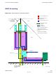
Access Point Hardware Installation Ground Cabling Installation RGPS Grounding Figure 4-6 Typical Outdoor Grounding Diagram DC Primary Surge Arrestors Backhaul & Customer I/O Surge Arrestor 45 Degree IEC Recommended Direct Strike Protection Angle AC Primary Surge Protector LPZ0A Bonded Ground / Earth Connection RF 1 RF 2 Conduit or Shielded Cable RF 3 LPZ0A -- Possible direct strike zone LPZ 2 LPZ0B -- No direct strike, but unattenuated electromagnetic field present LPZ 2 LPZ 2 LPZ1 Primary Pr
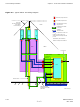
Ground Cabling Installation Chapter 4: Access Point Hardware Installation Figure 4-7 Typical Indoor Grounding Diagram DCPrimary Surge Arrestors Secondary Surge Arrestor 45 Degree IEC Recommended Direct Strike Protection Angle AC & Backhaul Primary Surge Arrestor LPZ0A Bonded Ground / Earth Connection RF 1 RF 2 Conduit or Shielded Cable RF 3 LPZ0A -- Possible direct strike zone LPZ 2 LPZ0B -- No direct strike, but unattenuated electromagnetic field present LPZ 2 LPZ 2 LPZ1 Primary Protected Zon
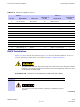
Access Point Hardware Installation AC Power Cabling Installation AC Power Cabling Installation ■ ■ ■ ■ ■ ■ ■ ■ ■ ■ ■ ■ ■ ■ ■ ■ ■ ■ ■ ■ ■ ■ ■ ■ ■ ■ ■ ■ ■ ■ ■ ■ ■ ■ ■ ■ ■ ■ ■ ■ ■ ■ ■ ■ ■ ■ ■ ■ ■ ■ ■ ■ ■ ■ ■ ■ ■ ■ ■ ■ ■ ■ ■ ■ Objective This section contains the procedure for installing the AC power cable. This equipment uses dangerous voltages and is capable of causing death. Use extreme caution when handling and testing this equipment.
AC Power Cabling Installation Chapter 4: Access Point Hardware Installation Procedure 4-4 Procedure to Install AC Power Cable 1 Ensure that AC power at the source is disabled before handling cable. 2 If not already done, route AC power cables through conduit to BCU Customer Interface compartment. 3 In the BCU Customer Interface compartment, open the AC power cover, by loosening two captive screws. AC Power cover is hinged. 4 Loosen screws on AC power circuit breaker terminal block.
Access Point Hardware Installation RF Head DC Power Cabling Installation RF Head DC Power Cabling Installation ■ ■ ■ ■ ■ ■ ■ ■ ■ ■ ■ ■ ■ ■ ■ ■ ■ ■ ■ ■ ■ ■ ■ ■ ■ ■ ■ ■ ■ ■ ■ ■ ■ ■ ■ ■ ■ ■ ■ ■ ■ ■ ■ ■ ■ ■ ■ ■ ■ ■ ■ ■ ■ ■ ■ ■ ■ ■ ■ ■ ■ ■ ■ ■ Objective This section contains the procedure for installing the RF Head DC power cables.
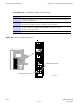
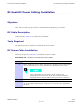
RF Head DC Power Cabling Installation Figure 4-9 Chapter 4: Access Point Hardware Installation Base Control Unit DC Power Connection CAUTION LIVE TERMINALS RFU 1 RFU 2 RFU 3 RFU 1, RFU 2, RFU 3, RFU4 4-26 RETURN +54VDC RETURN +54VDC RETURN +54VDC RETURN +54VDC CAUTION PRIOR TO INSTALLATION/REMOVAL OF WIRE TO TERMINAL BLOCK. ASSOCIATED CIRCUIT BREAKER TO BE DISENGAGED RFU 4 ti-cdma-04183.
Access Point Hardware Installation Antenna Cabling Installation Antenna Cabling Installation ■ ■ ■ ■ ■ ■ ■ ■ ■ ■ ■ ■ ■ ■ ■ ■ ■ ■ ■ ■ ■ ■ ■ ■ ■ ■ ■ ■ ■ ■ ■ ■ ■ ■ ■ ■ ■ ■ ■ ■ ■ ■ ■ ■ ■ ■ ■ ■ ■ ■ ■ ■ ■ ■ ■ ■ ■ ■ ■ ■ ■ ■ ■ ■ Objective This section contains the procedure for installing the antenna cables. Installing Antenna Cables The antenna cables will already be installed between the antenna and the RF Head.
RGPS Cabling Installation Chapter 4: Access Point Hardware Installation RGPS Cabling Installation ■ ■ ■ ■ ■ ■ ■ ■ ■ ■ ■ ■ ■ ■ ■ ■ ■ ■ ■ ■ ■ ■ ■ ■ ■ ■ ■ ■ ■ ■ ■ ■ ■ ■ ■ ■ ■ ■ ■ ■ ■ ■ ■ ■ ■ ■ ■ ■ ■ ■ ■ ■ ■ ■ ■ ■ ■ ■ ■ ■ ■ ■ ■ ■ Objective This section contains procedures for installing the Remote Global Positioning System (RGPS). Cable Description Cables C and C1 as listed inTable 3-1 are required for installation.
Access Point Hardware Installation RGPS Cabling Installation Table 4-4 Pinout for Cables C and C1 Cable C Pin No. Cable C1 Signal Name Connector A Pin No.
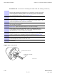
RGPS Cabling Installation Chapter 4: Access Point Hardware Installation Procedure 4-6 Procedure for Installing the RGPS Head and Cabling (Continued) Mounting the RGPS head and hardware to an inadequate wall structure and/or using inadequate installment methods can result in serious personal injury. Use the appropriate mounting bolts for the mounting surface and install the two wall mounting brackets. Refer to Figure 4-12.
Access Point Hardware Installation RGPS Cabling Installation Figure 4-12 Installing the Remote GPS Head RGPS HEAD WITH 12 PIN MALE CONNECTOR RGPS HEAD (MOTOROLA PART NUMBER 0186012H04)1 MATING CONNECTORS RGPS INTERFACE CABLE WITH 12 PIN FEMALE CONNECTOR ON ONE END AND UNTERMINATED WIRE ON OTHER END REFER TO VIEW A CABLE TO LIGHTNING ARRESTOR (CABLE C) VIEW A U--BOLTS CLAMP BRACKETS (2) CABLE TO LIGHTNING ARRESTOR (CABLE C) WALL MOUNTING BRACKETS (2) ti-cdma-04188.
RGPS Cabling Installation Chapter 4: Access Point Hardware Installation Figure 4-13 RGPS to Base Control Unit Connection Diagram RGPS HEAD (MOTOROLA P/N 0186012H04) 1 10 2 3 D--CONNECTOR TO BCU 9 11 8 12 UNUSED 5 Red/Black Red C Brown 1 12 4 10 2 Blue 8 Yellow 7 Blue/Black 15 Yellow/Black 14 Green 6 4 9 Green/Black 7 C1 RGPS CABLE CONNECTOR (VIEWED FROM CABLE PERSPECTIVE) CABLE DRAIN White/Black White Brown/Black Earth Ground CELL SITE GROUND = LIGHTNING ARRESTOR (WNP CGDSO
Access Point Hardware Installation Figure 4-14 RGPS Cabling Installation RGPS Lightning Arrestor Wiring Yellow/Black Yellow Green White/Black White Cable Drain Brown/Black Brown +17V DC Lines Red Blue Yellow/Black Yellow Green/Black Green White/Black White Cable Drain +17V DC Equipm ent Red/Black Blue/Black C (RGPS) TO RGPS RECEIVER +17V DC Lines Green/Black +17V DC Equipment C1 (RGPS) TO BCU UNIT +40V DC Lines Blue + 40V DC E quipm ent Blue/Black Red/Black Blue 1 White/Black 2 Whi
RF GPS Cabling Installation Chapter 4: Access Point Hardware Installation RF GPS Cabling Installation ■ ■ ■ ■ ■ ■ ■ ■ ■ ■ ■ ■ ■ ■ ■ ■ ■ ■ ■ ■ ■ ■ ■ ■ ■ ■ ■ ■ ■ ■ ■ ■ ■ ■ ■ ■ ■ ■ ■ ■ ■ ■ ■ ■ ■ ■ ■ ■ ■ ■ ■ ■ ■ ■ ■ ■ ■ ■ ■ ■ ■ ■ ■ ■ Objective The objective of this procedure is to install the Local (RF) Global Positioning System (RF GPS) cabling. Tools and Materials provides the quantities and descriptions of the cables.
Access Point Hardware Installation RF GPS Cabling Installation Procedure 4-7 Procedure for Installing RF GPS Antenna and Cabling (Continued) 3 The roof structure on which the mounting pole is attached should be veried by a qualied structural engineer for the weight of the RF GPS engine and mounting hardware or under adverse conditions for the installation area Mounting the RF GPS antenna and hardware to an inadequate roof surface and/or using inadequate installation methods can result in serious injur
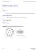
RF GPS Cabling Installation Chapter 4: Access Point Hardware Installation Procedure 4-7 Procedure for Installing RF GPS Antenna and Cabling (Continued) Figure 4-15 RF GPS Installation and Components Diagram NOTE: 1. TOTAL WEIGHT FOR GPS ANTENNA ASSEMBLY -- 0.65 LBS ANTENNA (GCNTM20A3A) (SEE NOTE 1) N CONNECTOR RUBBER PAD (P/O ANTENNA) ANTENNA IS DESIGNED FOR A 1--IN DIA. NOMINAL PIPE. THE ANTENNA CAN BE INSTALLED ON A 3/4--IN DIA.
Access Point Hardware Installation Ethernet Cabling Installation Ethernet Cabling Installation ■ ■ ■ ■ ■ ■ ■ ■ ■ ■ ■ ■ ■ ■ ■ ■ ■ ■ ■ ■ ■ ■ ■ ■ ■ ■ ■ ■ ■ ■ ■ ■ ■ ■ ■ ■ ■ ■ ■ ■ ■ ■ ■ ■ ■ ■ ■ ■ ■ ■ ■ ■ ■ ■ ■ ■ ■ ■ ■ ■ ■ ■ ■ ■ Objective This section contains the procedure for installing the ethernet cables. Cable Description Cable J as listed in Table 3-1 is required for installation.
Fiber Optic Cabling Installation Chapter 4: Access Point Hardware Installation Fiber Optic Cabling Installation ■ ■ ■ ■ ■ ■ ■ ■ ■ ■ ■ ■ ■ ■ ■ ■ ■ ■ ■ ■ ■ ■ ■ ■ ■ ■ ■ ■ ■ ■ ■ ■ ■ ■ ■ ■ ■ ■ ■ ■ ■ ■ ■ ■ ■ ■ ■ ■ ■ ■ ■ ■ ■ ■ ■ ■ ■ ■ ■ ■ ■ ■ ■ ■ Objective This section contains the procedure for installing the fiber optic cables. Cable Description Cable H as listed in Table 3-1 is required for installation.
Access Point Hardware Installation Customer Input/Output Cabling Installation Customer Input/Output Cabling Installation ■ ■ ■ ■ ■ ■ ■ ■ ■ ■ ■ ■ ■ ■ ■ ■ ■ ■ ■ ■ ■ ■ ■ ■ ■ ■ ■ ■ ■ ■ ■ ■ ■ ■ ■ ■ ■ ■ ■ ■ ■ ■ ■ ■ ■ ■ ■ ■ ■ ■ ■ ■ ■ ■ ■ ■ ■ ■ ■ ■ ■ ■ ■ ■ Objective This section contains the procedures for installing the Customer Defined Input/Output cables. Cable Descriptions Cable F as listed inTable 3-1 is required for installation.
Customer Input/Output Cabling Installation Chapter 4: Access Point Hardware Installation 4-40 68P09277A59-5 Draft OCT 2006
Chapter 5 Optional Equipment ■ ■ ■ ■ ■ ■ ■ ■ ■ ■ ■ ■ ■ ■ ■ ■ ■ ■ ■ ■ ■ ■ ■ ■ ■ ■ ■ ■ ■ ■ ■ ■ ■ ■ ■ ■ ■ ■ ■ ■ ■ ■ ■ ■ ■ ■ ■ ■ ■ ■ ■ ■ ■ ■ ■ ■ ■ ■ ■ ■ ■ ■ ■ ■ ■ ■ 68P09277A59-5 OCT 2006 5-1 Draft
Optional Band Pass Filters Chapter 5: Optional Equipment Optional Band Pass Filters ■ ■ ■ ■ ■ ■ ■ ■ ■ ■ ■ ■ ■ ■ ■ ■ ■ ■ ■ ■ ■ ■ ■ ■ ■ ■ ■ ■ ■ ■ ■ ■ ■ ■ ■ ■ ■ ■ ■ ■ ■ ■ ■ ■ ■ ■ ■ ■ ■ ■ ■ ■ ■ ■ ■ ■ ■ ■ ■ ■ ■ ■ ■ ■ Overview This chapter contains general information and procedures for installing optional equipment. Band pass filters are available as optional equipment to accommodate customers with specific band allocations.
Access Point Hardware Installation Motorola Stability Oscillator (MSO) Motorola Stability Oscillator (MSO) ■ ■ ■ ■ ■ ■ ■ ■ ■ ■ ■ ■ ■ ■ ■ ■ ■ ■ ■ ■ ■ ■ ■ ■ ■ ■ ■ ■ ■ ■ ■ ■ ■ ■ ■ ■ ■ ■ ■ ■ ■ ■ ■ ■ ■ ■ ■ ■ ■ ■ ■ ■ ■ ■ ■ ■ ■ ■ ■ ■ ■ ■ ■ ■ Overview The Motorola Stability Oscillator (MSO) is available as optional equipment to accommodate customers that want this backup timing module.
Motorola Stability Oscillator (MSO) Chapter 5: Optional Equipment 5-4 68P09277A59-5 Draft OCT 2006
Chapter 6 What’s Next and Cleanup ■ ■ ■ ■ ■ ■ ■ ■ ■ ■ ■ ■ ■ ■ ■ ■ ■ ■ ■ ■ ■ ■ ■ ■ ■ ■ ■ ■ ■ ■ ■ ■ ■ ■ ■ ■ ■ ■ ■ ■ ■ ■ ■ ■ ■ ■ ■ ■ ■ ■ ■ ■ ■ ■ ■ ■ ■ ■ ■ ■ ■ ■ ■ ■ ■ ■ 68P09277A59-5 OCT 2006 6-1 Draft
What’s Next Chapter 6: What’s Next and Cleanup What’s Next ■ ■ ■ ■ ■ ■ ■ ■ ■ ■ ■ ■ ■ ■ ■ ■ ■ ■ ■ ■ ■ ■ ■ ■ ■ ■ ■ ■ ■ ■ ■ ■ ■ ■ ■ ■ ■ ■ ■ ■ ■ ■ ■ ■ ■ ■ ■ ■ ■ ■ ■ ■ ■ ■ ■ ■ ■ ■ ■ ■ ■ ■ ■ ■ Introduction Optimization is the next procedure you should perform. There are two things left to do before you begin the optimization: 1. Clean up the site 2.
Access Point Hardware Installation Site Cleanup Site Cleanup ■ ■ ■ ■ ■ ■ ■ ■ ■ ■ ■ ■ ■ ■ ■ ■ ■ ■ ■ ■ ■ ■ ■ ■ ■ ■ ■ ■ ■ ■ ■ ■ ■ ■ ■ ■ ■ ■ ■ ■ ■ ■ ■ ■ ■ ■ ■ ■ ■ ■ ■ ■ ■ ■ ■ ■ ■ ■ ■ ■ ■ ■ ■ ■ Tools Place all hand and power tools in the installation tool kit or other appropriate place. Note any tools that need replacement, cleaning, or adjustment. Materials Place any leftover materials in a location specified by the site manager.
Installation Completion Checklist Chapter 6: What’s Next and Cleanup Installation Completion Checklist ■ ■ ■ ■ ■ ■ ■ ■ ■ ■ ■ ■ ■ ■ ■ ■ ■ ■ ■ ■ ■ ■ ■ ■ ■ ■ ■ ■ ■ ■ ■ ■ ■ ■ ■ ■ ■ ■ ■ ■ ■ ■ ■ ■ ■ ■ ■ ■ ■ ■ ■ ■ ■ ■ ■ ■ ■ ■ ■ ■ ■ ■ ■ ■ Installation Completion Checklist Check the items listed in Table 6-1. Directions Fill out the installation completion checklist and make any necessary copies. You may copy this check sheet as needed.
Access Point Hardware Installation Installation Completion Checklist Table 6-1 Hardware Installation Checklist Item No. Item Notes 1 Equipment is not damaged. 2 Air flow clearance requirements are met. 3 Base Control Unit (BCU) is securely mounted to wall or pole. 4 BCU and RF Carrier Unit (RFCU) are RF cabled correctly. 5 BCU and RFCU are DC power cabled correctly. 6 BCU is ethernet cabled. (If installed) 7 RF Head is securely mounted to pole.
Installation Completion Checklist Chapter 6: What’s Next and Cleanup 6-6 68P09277A59-5 Draft OCT 2006
Appendix A Alternate Installation Procedures 68P09277A59-5 OCT 2006 A-1 Draft
Manual RF Head Installation Procedures Appendix A: Alternate Installation Procedures Manual RF Head Installation Procedures ■ ■ ■ ■ ■ ■ ■ ■ ■ ■ ■ ■ ■ ■ ■ ■ ■ ■ ■ ■ ■ ■ ■ ■ ■ ■ ■ ■ ■ ■ ■ ■ ■ ■ ■ ■ ■ ■ ■ ■ ■ ■ ■ ■ ■ ■ ■ ■ ■ ■ ■ ■ ■ ■ ■ ■ ■ ■ ■ ■ ■ ■ ■ ■ Overview This section contains the procedures for installing the Diversity Access Point RF Head which is comprised of the TRX Module and antenna radome. Refer to Figure 1–2.
Access Point Hardware Installation Manual RF Head Installation Procedures Tools and Materials • Mounting Bracket Assembly • U-bolts • Set of metric sockets (3/8–in or 1/4–in) • Set of standard sockets (3/8–in or 1/4–in) • 3/8–in or 1/4–in driver • Torque Driver • Cordless Power Driver • Ground Lug • Crimp Tool • T30 Torx Screw Driver • Adjustable Crescent Wrench U-Bolt Specications Reference Figure A-1 and Table A-2 to determine the proper U-bolt to use.
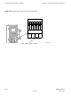
Manual RF Head Installation Procedures Figure A-2 Appendix A: Alternate Installation Procedures RF Head Mounting Bracket Assembly ti-cdma-04179.eps RF Head Mounting Bracket Assembly Procedure Follow the steps in Procedure A-1 to install the pole mounting bracket for the RF Head.
Access Point Hardware Installation Manual RF Head Installation Procedures Procedure A-1 Procedure to Install RF Head Main Support Bracket Assembly 1 Remove nuts and plate (or washers) from both ends of the U-bolt. 2 Set Main Support Bracket Assembly at the required height. It is recommended that two people perform attach the bracket to the pole. 3 Slide first U-bolt around pole and through top slots of Main Support Bracket Assembly. Slide plate (or washers) over threads.
Manual RF Head Installation Procedures Procedure A-2 Appendix A: Alternate Installation Procedures Procedure to Install the RF Head (Continued) 7 Install the antenna (Radome). Hook the antenna top support brackets over the bolts near the top of the RF Head. Loosen antenna hook bolts as required. Push the bottom of the antenna and hook those brackets over the bolts near the bottom of the RF Head. 8 Secure antenna using a 10 mm socket and driver to tighten the 4 screws.
Access Point Hardware Installation Procedure A-2 Manual RF Head Installation Procedures Procedure to Install the RF Head (Continued) 17 Attach solar shield. Insert mushroom head knobs near bottom of shield into keyhole slots on sides of mounting bracket. Slide solar shield into position over handle and into slots on top of mounting bracket. Tighten screws to secure shield to brackets. 18 Prepare the RF Head for hoisting. Attach carabiner to handle of RF Head.
Manual RF Head Installation Procedures Appendix A: Alternate Installation Procedures Figure A-3 RF Head Side Mounting Brackets and Solar Shield ti-cdma-04195.eps Procedure A-3 Procedure to Install Optional RF Filter 1 From Procedure A-2 , step 3 , attach the filter mounting plate to the rear of the RF Filter using four screws. Torque screws to 45 in-lbs (5 N-m). 2 Hook filter mounting plate to side support brackets.
Access Point Hardware Installation Manual RF Head Installation Procedures Figure A-4 Antenna to Filter RF Cable Connection Diagram ti-cdma-04200.