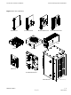
Access Point Hardware Installation Access Point Equipment Identication Figure 1-3 BCU Hardware Alarm Card Controller Card Modem Card Card Circuit Breaker Card PSU Heater Fan Tray I/O Panel Pole Mount Bracket BCU Chassis 68P09277A59-5 ti-cdma-04197.
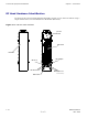
Access Point Equipment Identication Chapter 1: Introduction RF Head Hardware Identication The Diversity Access Point (DAP) RF Head Assembly consists of a two antenna element using a single radome and a (one Transmit/Receive RF Module (RF Head)). Figure 1-4 DAP RF Head Hardware Access Panel RF Head Radome Fiber Optic Ground RF Connector RF Connector ti-cdma-04168.
Chapter 2 Site Preparation ■ ■ ■ ■ ■ ■ ■ ■ ■ ■ ■ ■ ■ ■ ■ ■ ■ ■ ■ ■ ■ ■ ■ ■ ■ ■ ■ ■ ■ ■ ■ ■ ■ ■ ■ ■ ■ ■ ■ ■ ■ ■ ■ ■ ■ ■ ■ ■ ■ ■ ■ ■ ■ ■ ■ ■ ■ ■ ■ ■ ■ ■ ■ ■ ■ ■ 68P09277A59-5 OCT 2006 2-1 Draft
Site Preparation Overview Chapter 2: Site Preparation Site Preparation Overview ■ ■ ■ ■ ■ ■ ■ ■ ■ ■ ■ ■ ■ ■ ■ ■ ■ ■ ■ ■ ■ ■ ■ ■ ■ ■ ■ ■ ■ ■ ■ ■ ■ ■ ■ ■ ■ ■ ■ ■ ■ ■ ■ ■ ■ ■ ■ ■ ■ ■ ■ ■ ■ ■ ■ ■ ■ ■ ■ ■ ■ ■ ■ ■ Overview This chapter provides the procedures and information to verify that the site is ready for equipment installation.
Access Point Hardware Installation Prepare Site for Equipment Arrival Prepare Site for Equipment Arrival ■ ■ ■ ■ ■ ■ ■ ■ ■ ■ ■ ■ ■ ■ ■ ■ ■ ■ ■ ■ ■ ■ ■ ■ ■ ■ ■ ■ ■ ■ ■ ■ ■ ■ ■ ■ ■ ■ ■ ■ ■ ■ ■ ■ ■ ■ ■ ■ ■ ■ ■ ■ ■ ■ ■ ■ ■ ■ ■ ■ ■ ■ ■ ■ Description This information covers various topics not all of which are needed at every site. Based on the site characteristics execute the steps that apply to your site.
Shipping and Handling Chapter 2: Site Preparation Shipping and Handling ■ ■ ■ ■ ■ ■ ■ ■ ■ ■ ■ ■ ■ ■ ■ ■ ■ ■ ■ ■ ■ ■ ■ ■ ■ ■ ■ ■ ■ ■ ■ ■ ■ ■ ■ ■ ■ ■ ■ ■ ■ ■ ■ ■ ■ ■ ■ ■ ■ ■ ■ ■ ■ ■ ■ ■ ■ ■ ■ ■ ■ ■ ■ ■ Overview The purpose of this chapter is to describe how the Base Control Unit (BCU) and RF Head are packaged for shipping and how to correctly unpack the units in preparation for installation.
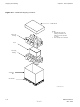
Access Point Hardware Installation Table 2-1 Shipping and Handling Recommended Unpacking Tools Description Qty 1 Tin snips 1 Knife, box cutter, scissors Unpacking Diagrams The following diagrams show how to unpack the equipment. Figure 2-1 Shrink Wrapped Shipment Authors Note: Figure 2–1 will be new and Figure 2–2 will be changed.
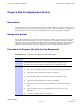
Shipping and Handling Chapter 2: Site Preparation Figure 2-2 Cardboard Shipping Container Cardboard Lid NOTE: 1. Normally this styrofoam packing is attached to the pallet. it is shown exploded for clarity 2. This example shows the BCU Styrofoam Packing BCU Styrofoam Packing1 Cardboard Box Wood Pallet ti-cdma-04170.
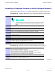
Access Point Hardware Installation Shipping and Handling Unpacking a Cardboard Container or Shrink Wrapped Shipment Follow the procedure in Procedure 2-2 to unpack equipment from a container or shrink wrap. Procedure 2-2 Unpacking Equipment from a Cardboard Container or Shrink Wrap 1 Inspect for damage. Components may or may not be delivered on one pallet. Procedure assumes components are delivered in separate containers on one pallet. 2 If container is made of cardboard, proceed to step 3.
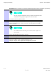
Shipping and Handling Chapter 2: Site Preparation Procedure 2-3 Procedure to Remove Outdoor Equipment from Container (Continued) 4 The BCU weighs a maximum of 68 kg (150 lbs). Recommend that a minimum of two people be present to move the BCU. Locate BCU door key. Remove BCU. 5 Use the key to open the door. Verify that cards and modules are installed. 6 If BCU is to be pole mounted, check that BCU has part of the mounting bracket already attached.
Chapter 3 Cable Descriptions ■ ■ ■ ■ ■ ■ ■ ■ ■ ■ ■ ■ ■ ■ ■ ■ ■ ■ ■ ■ ■ ■ ■ ■ ■ ■ ■ ■ ■ ■ ■ ■ ■ ■ ■ ■ ■ ■ ■ ■ ■ ■ ■ ■ ■ ■ ■ ■ ■ ■ ■ ■ ■ ■ ■ ■ ■ ■ ■ ■ ■ ■ ■ ■ ■ ■ 68P09277A59-5 OCT 2006 3-1 Draft